MODULE ĐIỀU KHIỂN ĐỘNG CƠ TB6612 TB6612FNG - BẢO VỆ QUÁ DÒNG
- Kho hàng: Còn hàng
- Thương hiệu: Chính hãng
MODULE ĐIỀU KHIỂN ĐỘNG CƠ TB6612 TB6612FNG - BẢO VỆ QUÁ DÒNG

Introduction to TB6612FNG:
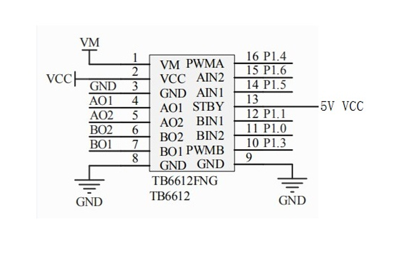
- The TB6612FNG is a DC motor drive device with a high current MOSFET-H bridge structure and a dual channel output that can drive two motors simultaneously.
- TB6612FNG output continuous driving current of 1 A per drunk, starting peak current up to 2A/3A (continuous pulse/single pulse); 4 kinds of motor control modes: forward/reverse/brake/stop; PWM support frequency up to 100 kHz; standby state; on-chip low-voltage detection circuit and thermal shutdown protection circuit; operating temperature: -20 ~ 85 ° C; SSOP24 small patch package.
- Main pin functions of TB6612FNG: AINl/AIN2, BIN1/BIN2, PWMA/PWMB are control signal input terminals; AO1/A02, B01/B02 are 2-way motor control output terminals; STBY is normal working/standby state control pin; The VM (3 to 13.5 V) and VCC (2.7 to 5.5 V) are the motor drive voltage input and the logic level input, respectively.
- The internal MOSFET-based H-bridge integrated circuit of the IC is much more efficient than the transistor H-bridge driver. Compared to the L293D's average drive current of 600 mA per channel and 1.2 A pulse peak current, its output load capacity is doubled. Compared with the heat dissipation of the L298N and the peripheral diode freewheeling circuit, it does not require an external heat sink, and the peripheral circuit is simple. Only an external power supply filter capacitor can directly drive the motor, which is beneficial to reduce the system size.For PWM signals, frequencies up to 100 kHz are also very advantageous compared to the 5 kHz and 40 kHz of the above two chips.
Sửa biến tần ABB | Sửa biến tần Schneider | Sửa biến tần Siemens | Sửa biến tần Danfoss | Sửa biến tần Yakawa | Sửa biến tần LS | Sửa biến tần INVT | Sửa biến tần Fuji | Sửa biến tần Emerson | Sửa biến tần Delta | Sửa biến tần Inovance | Sửa biến tần Hitachi | Sửa biến tần Delixi | Sửa biến tần Best | Sửa biến tần Sanch | Sửa biến tần Allen Bradley AB | Sửa biến tần KEB |
SỬA CHỮA BIẾN TẦN
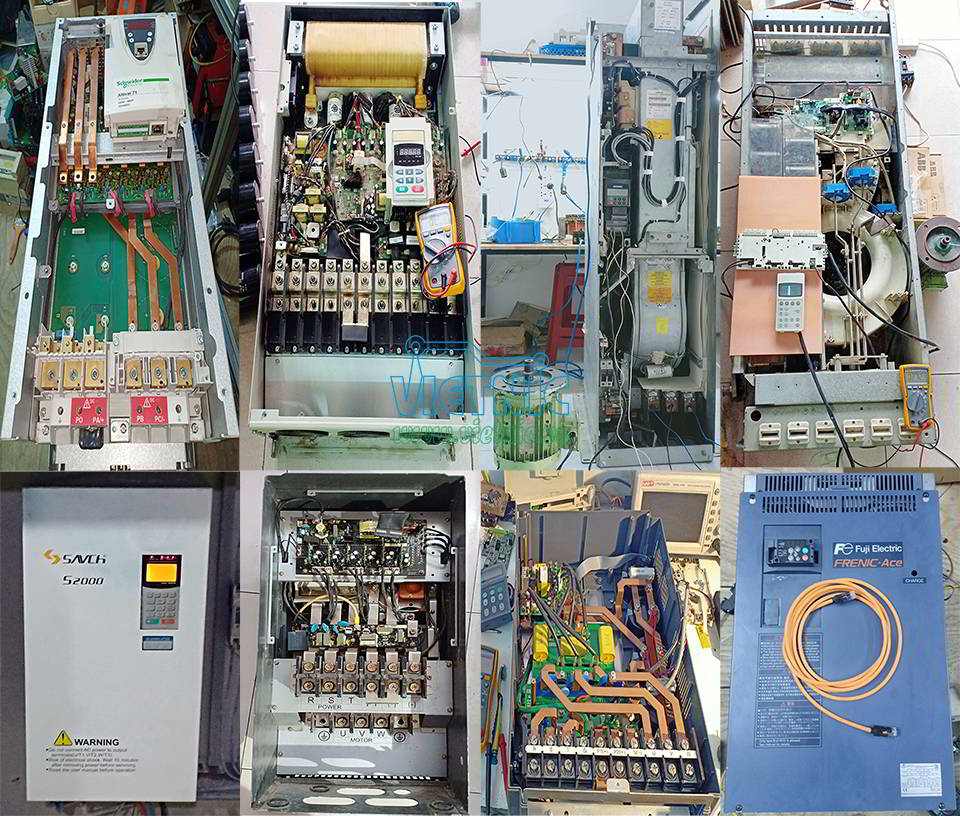

SỬA CHỮA BIẾN TẦN TẠI ĐÀ NẴNG
Sửa chữa biến tần ABB, Sửa chữa Biến tần Siemens, Biến tần Emersons, Biến tần Sneijder, Biến tần Yaskawa, Sữa chữa Biến tần LS, Sữa chữa biến tần Delta, Sữa chữa Biến tần INVT, Biến tần Lenze, Biến tần Fuji và các dòng biến tần như Biến tần Yolico, Biến tần Nowforever..........
- Sửa chữa biến tần lỗi nguồn, lỗi quá áp, lỗi quá dòng
- Sửa chữa biến tần lỗi lệch pha, hỏng công suất
- Cài đặt biến tần theo yêu cầu
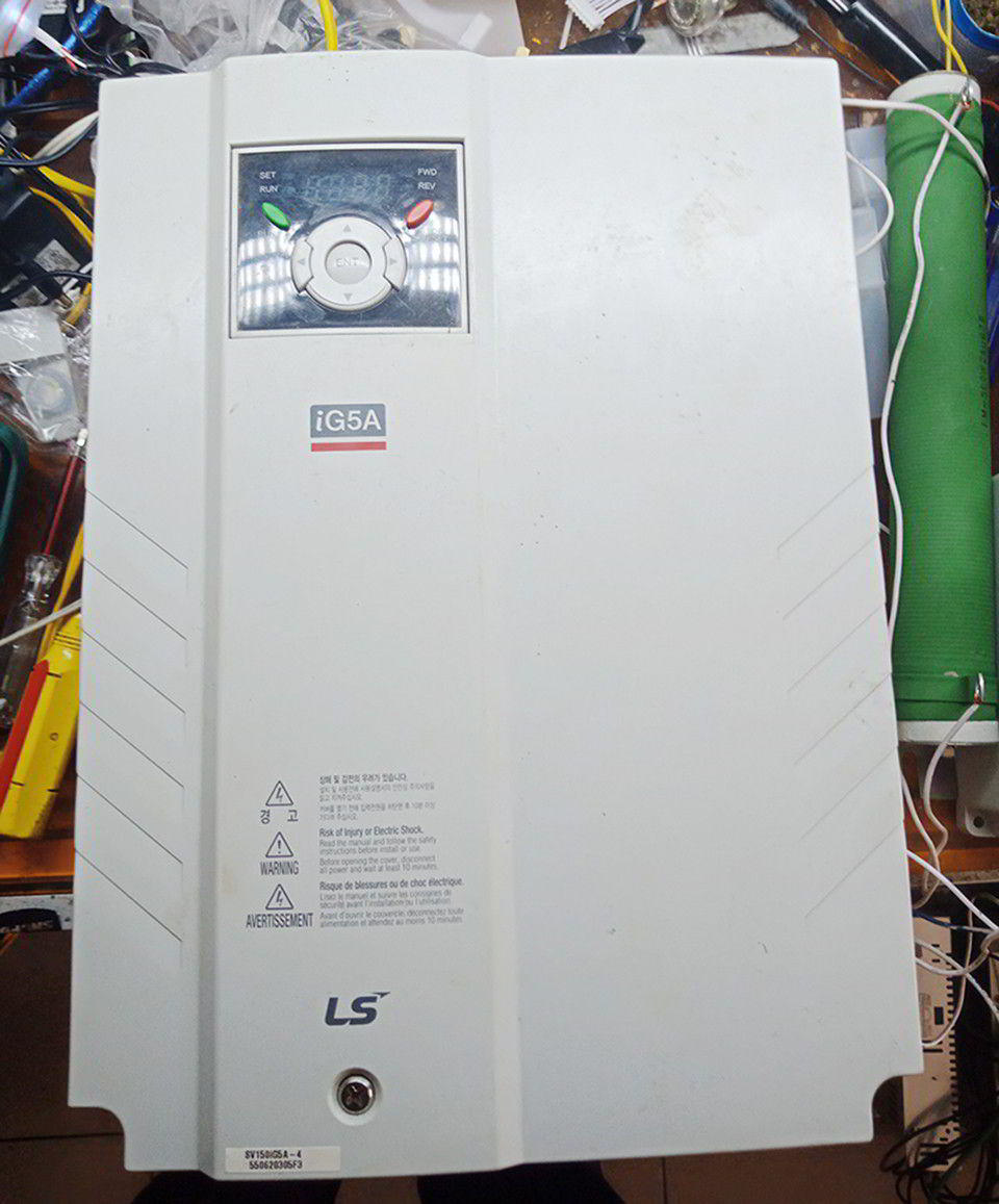
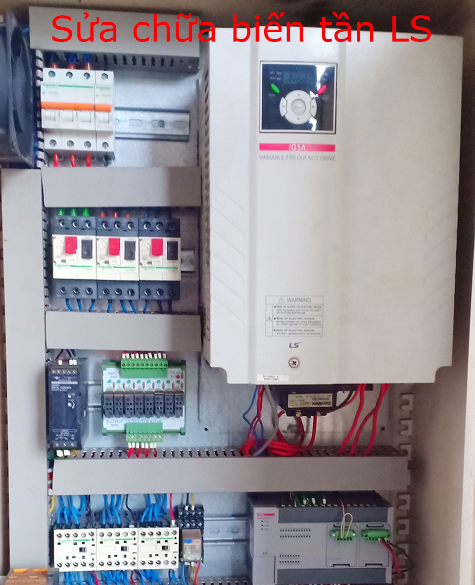
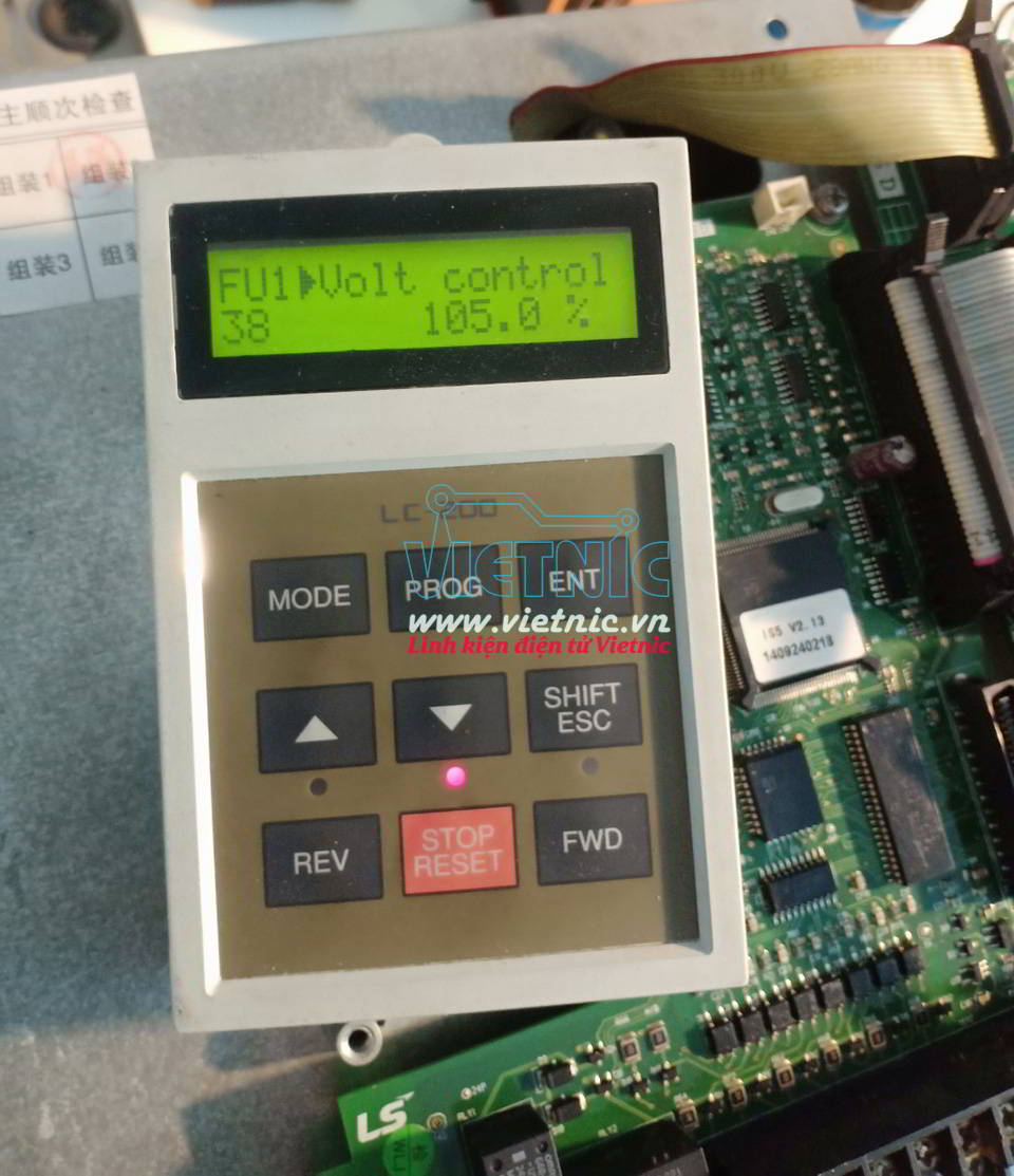
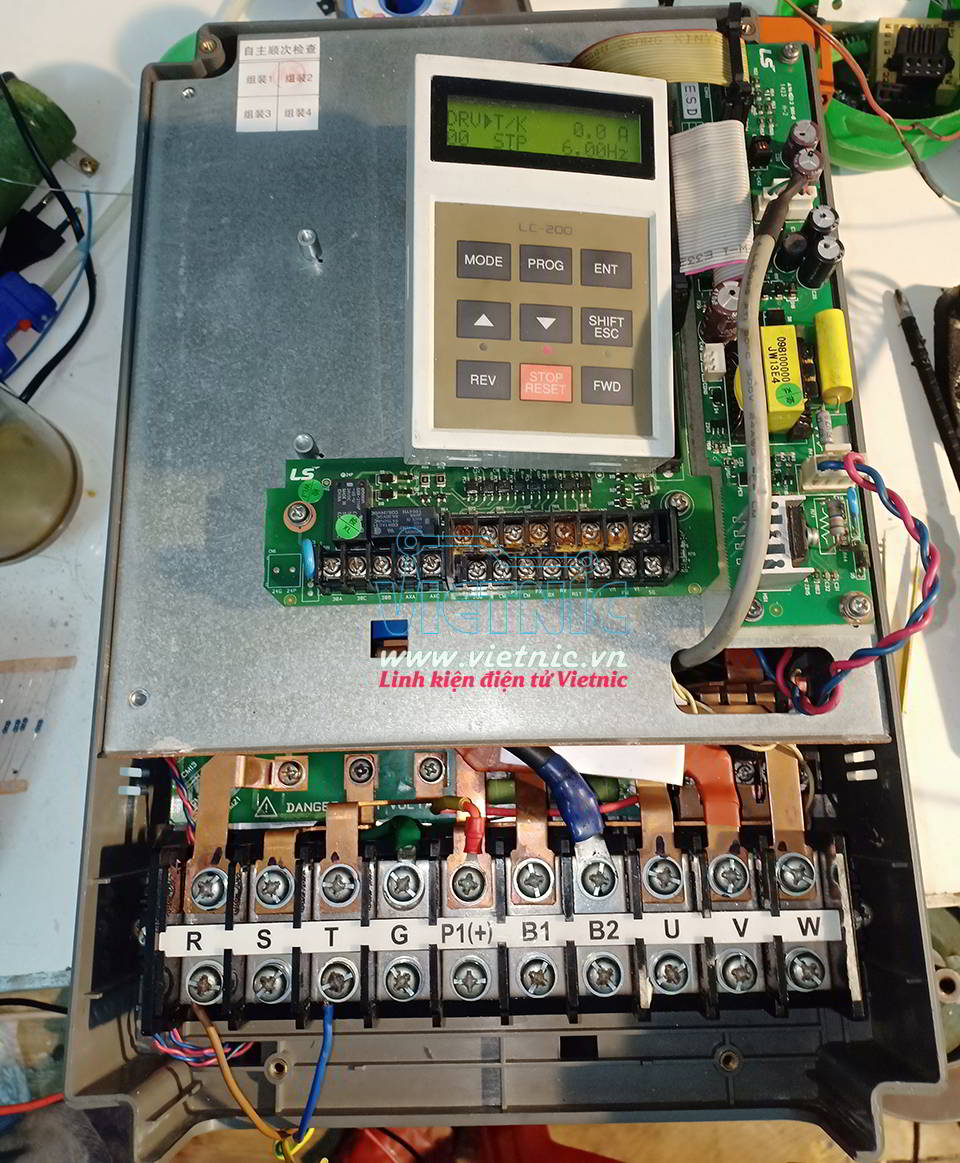
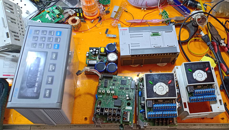
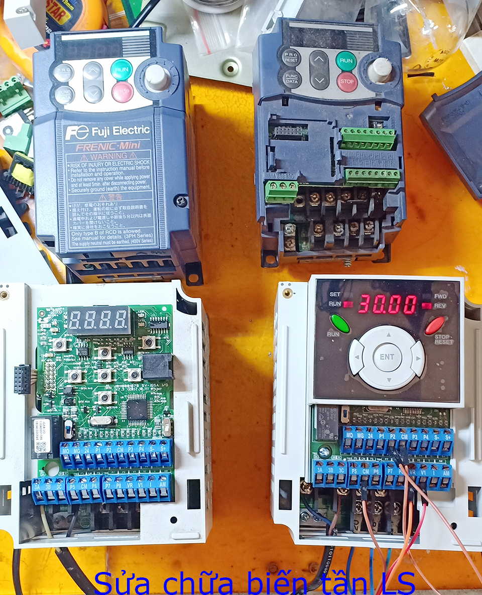
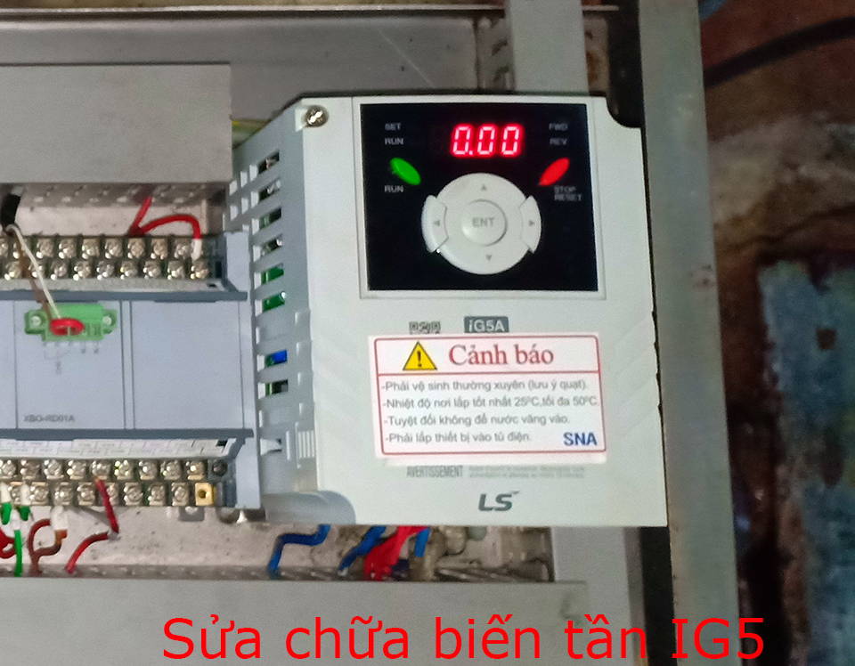
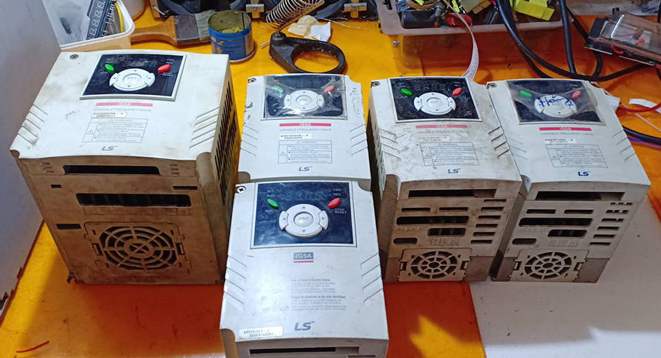
SỬA CHỮA BIẾN TẦN LS - SỬA CHỮA BIẾN TẦN IG5
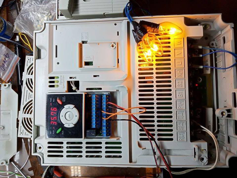
Sửa chữa biến tần LS các dòng 0.75KW đến 37KW lỗi nguồn điều khiển, Nguồn Bus DC, hỏng công suất, hỏng chỉnh lưu, thấp áp, quá áp, lỗi quá dòng, lỗi lệch pha

SỬA CHỮA BIẾN TẦN YASKAWA - SỬA CHỮA BIẾN TẦN H1000
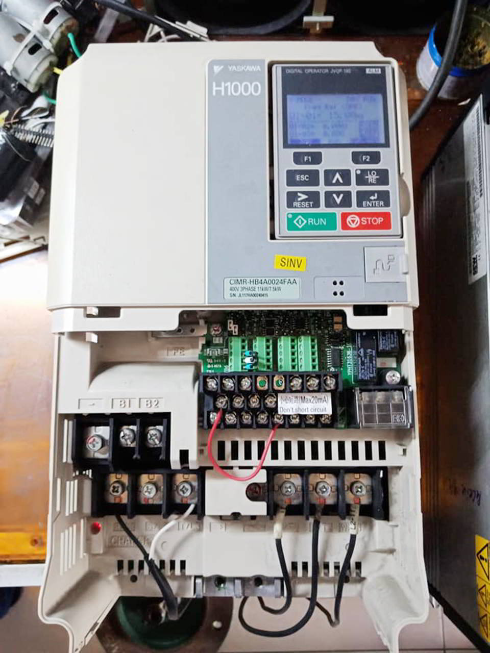
Sửa chữa biến tần yaskawa tại Đà Nẵng
Sửa chữa biến tần Yaskawa lỗi nguồn điều khiển, lỗi công suất, lỗi thấp áp, lỗi quá áp, lỗi quá dòng, lỗi lệch pha

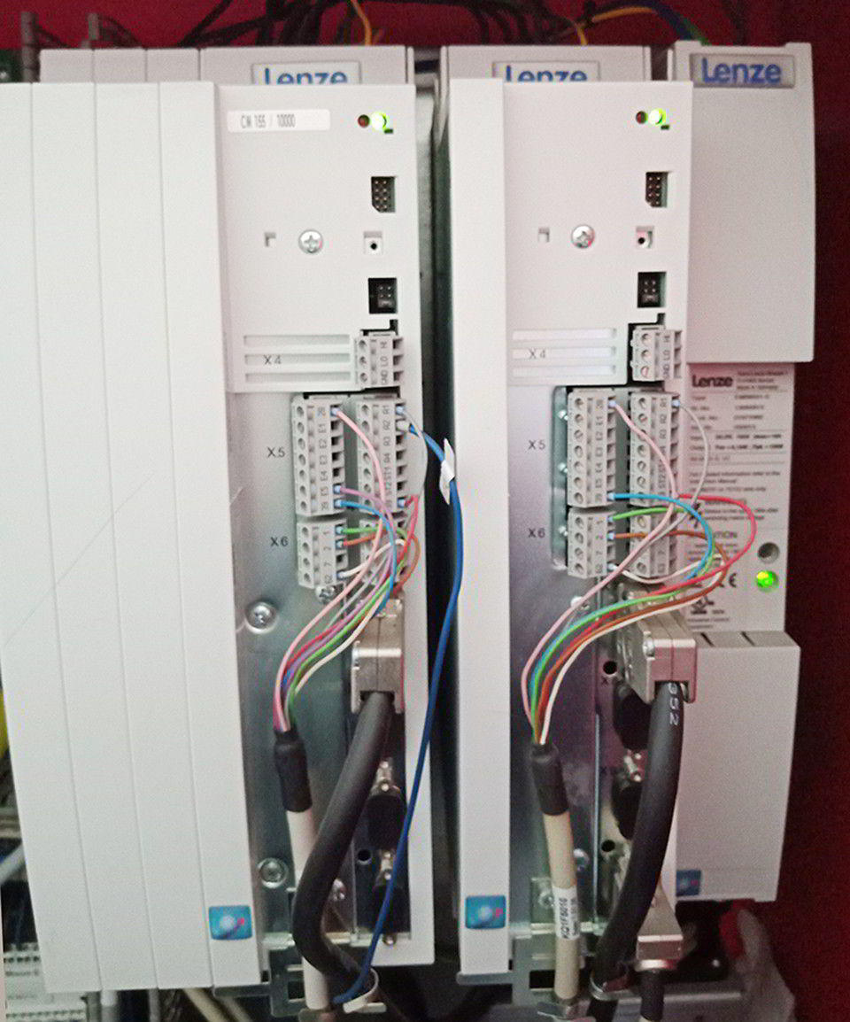
SỬA CHỮA BIẾN TẦN ĐÀ NẴNG - SỬA CHỮA BIẾN TẦN LENZE
Sửa chữa biến tần Lenze tại Đà Nẵng
SỬA CHỮA BIẾN TẦN DANFOSS TẠI ĐÀ NẴNG
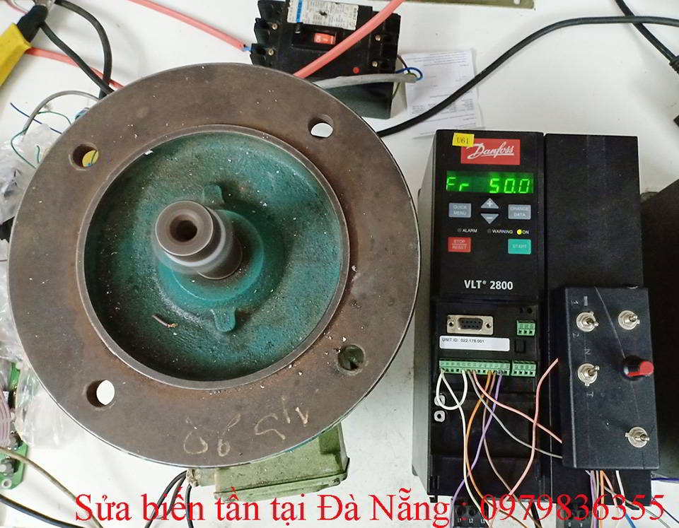
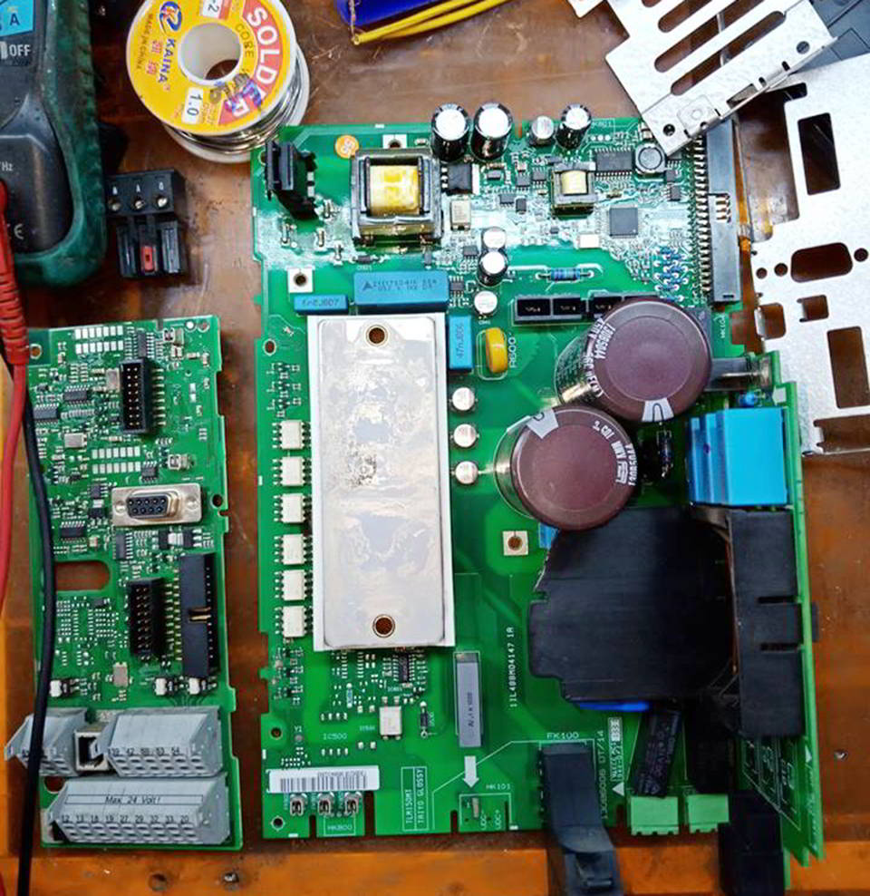
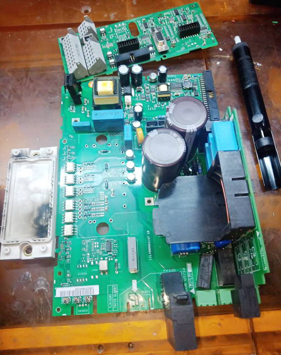
Sửa chữa biến tần danfoss
Sửa chữa biến tần Danfoss VLT2800, Sửa chữa biến tần Danfoss VLT2900
Sửa chữa biến tần Danfoss lỗi nguồn điều khiển, Nguồn Bus DC, hỏng công suất, lỗi thấp áp, lỗi quá áp, lỗi quá dòng, lỗi lệch pha

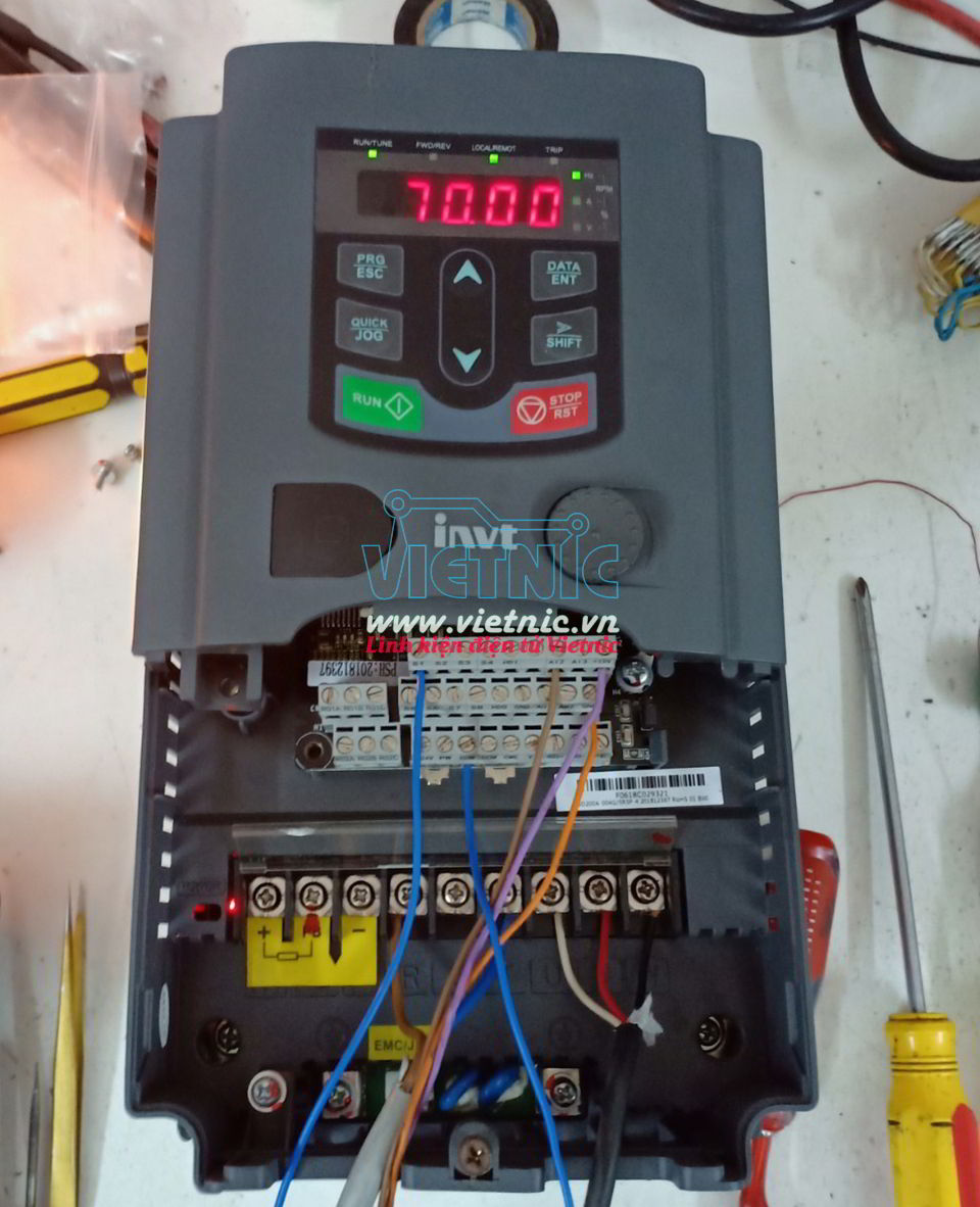
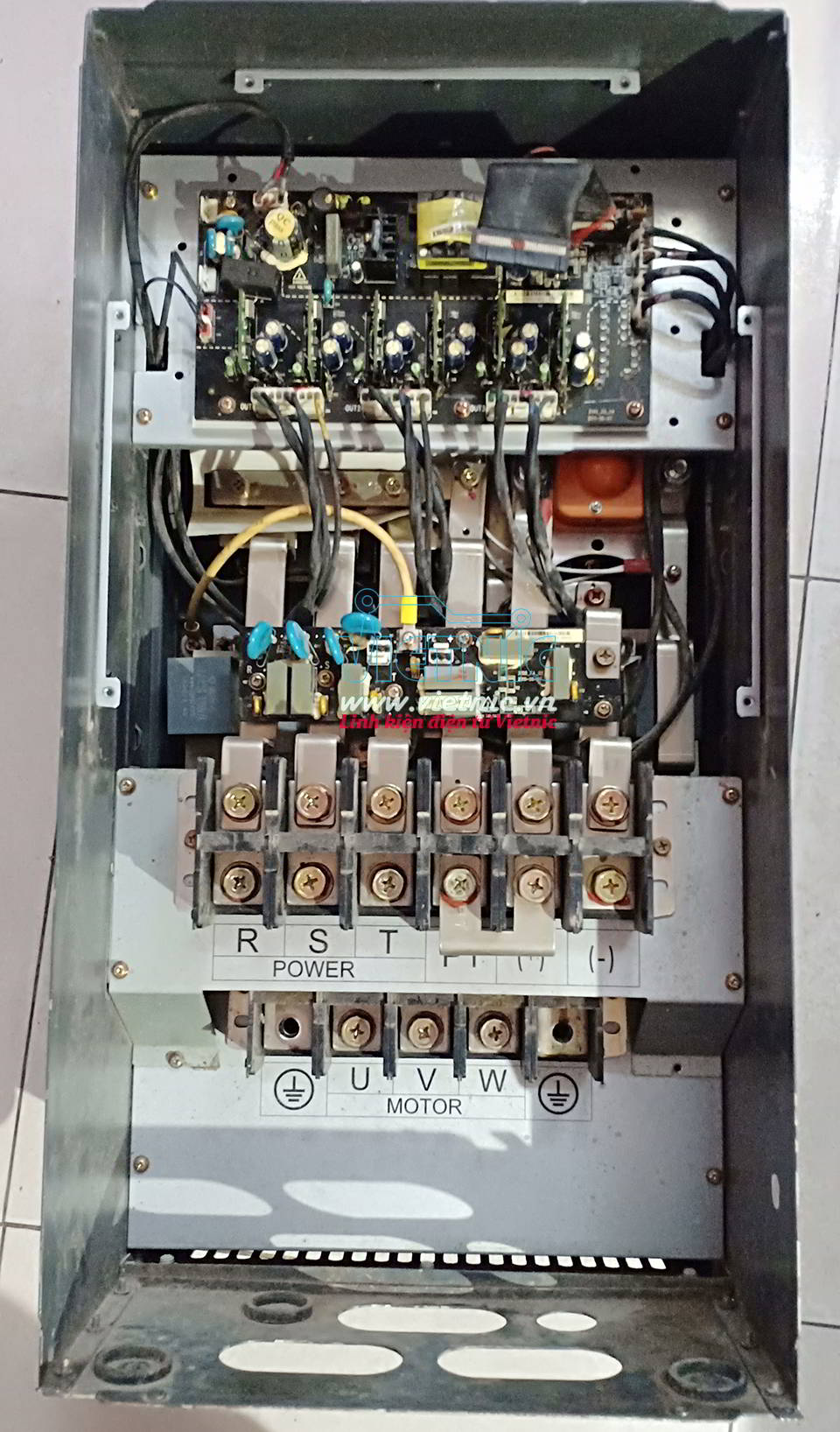
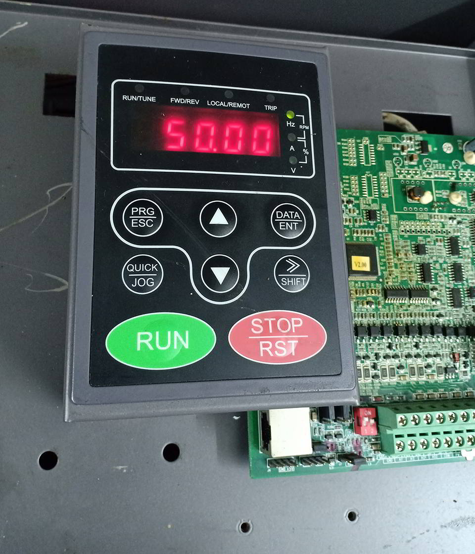
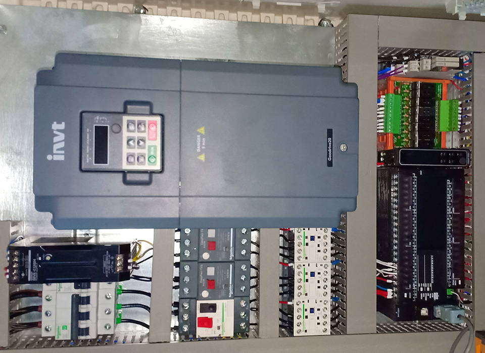
SỬA CHỮA BIẾN TẦN INVT
Sửa chữa biến tần INVT tại Đà Nẵng

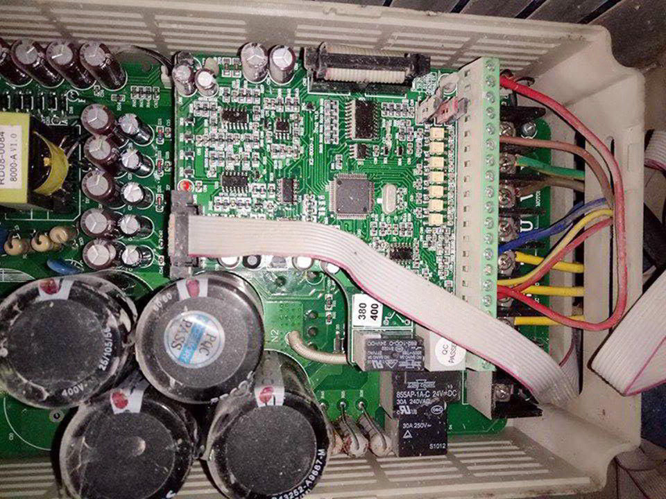
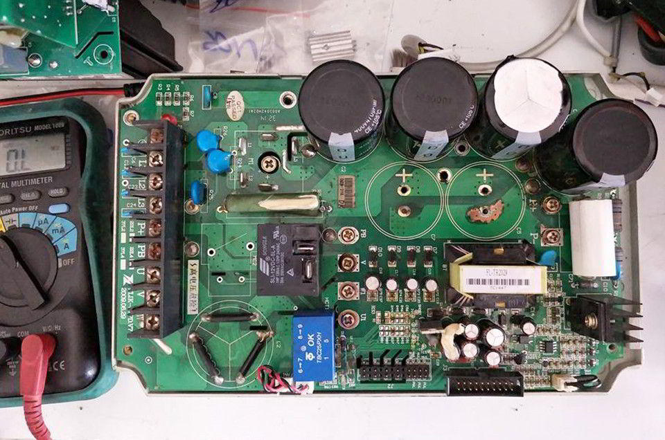
SỬA CHỮA BIẾN TẦN NOWFOREVER
Sửa chữa biến tần Nowforever tại Đà Nẵng
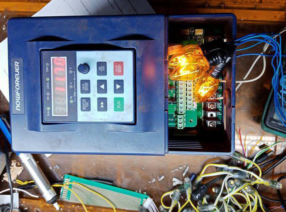
SỬA CHỮA BIẾN TẦN SIEMENS TẠI ĐÀ NẴNG
Sửa chữa biến tần Siemens tại Đà Nẵng

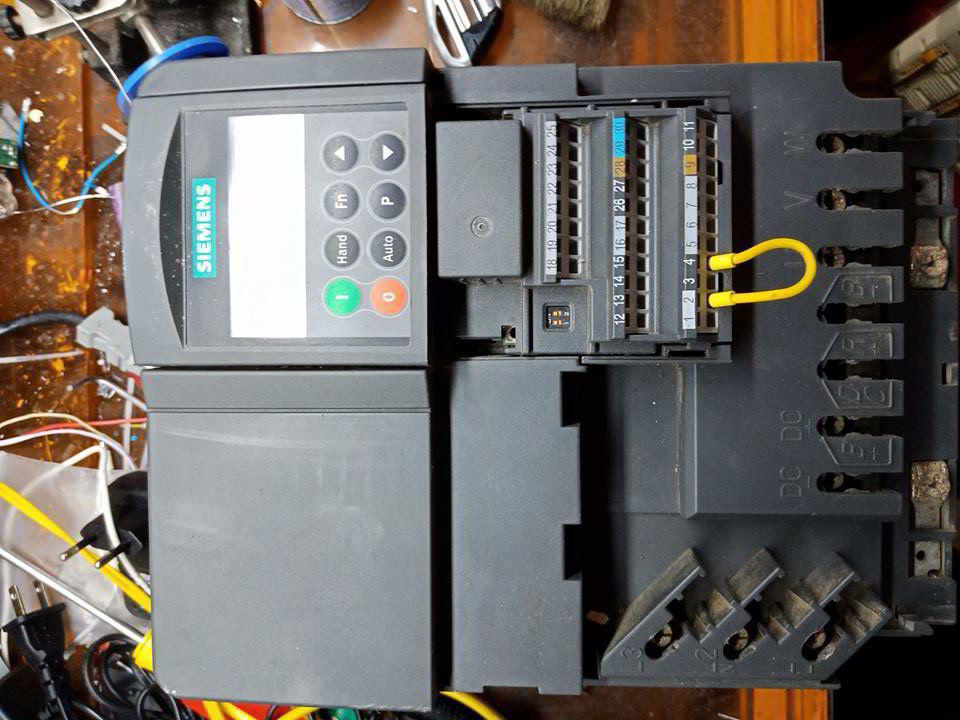
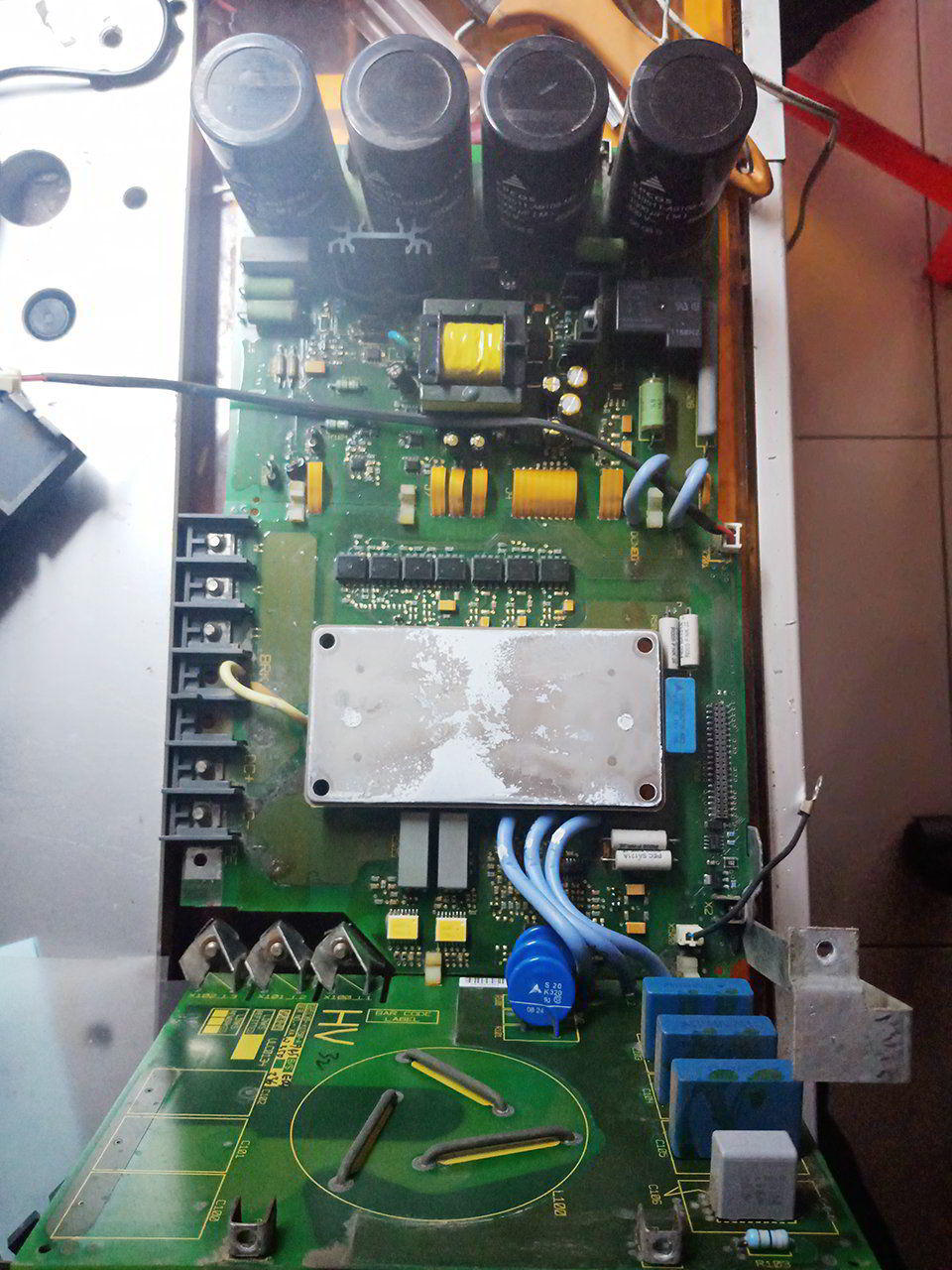
SỬA CHỮA BIẾN TẦN SAJ
Sửa chữa biến tần SAJ tại Đà Nẵng
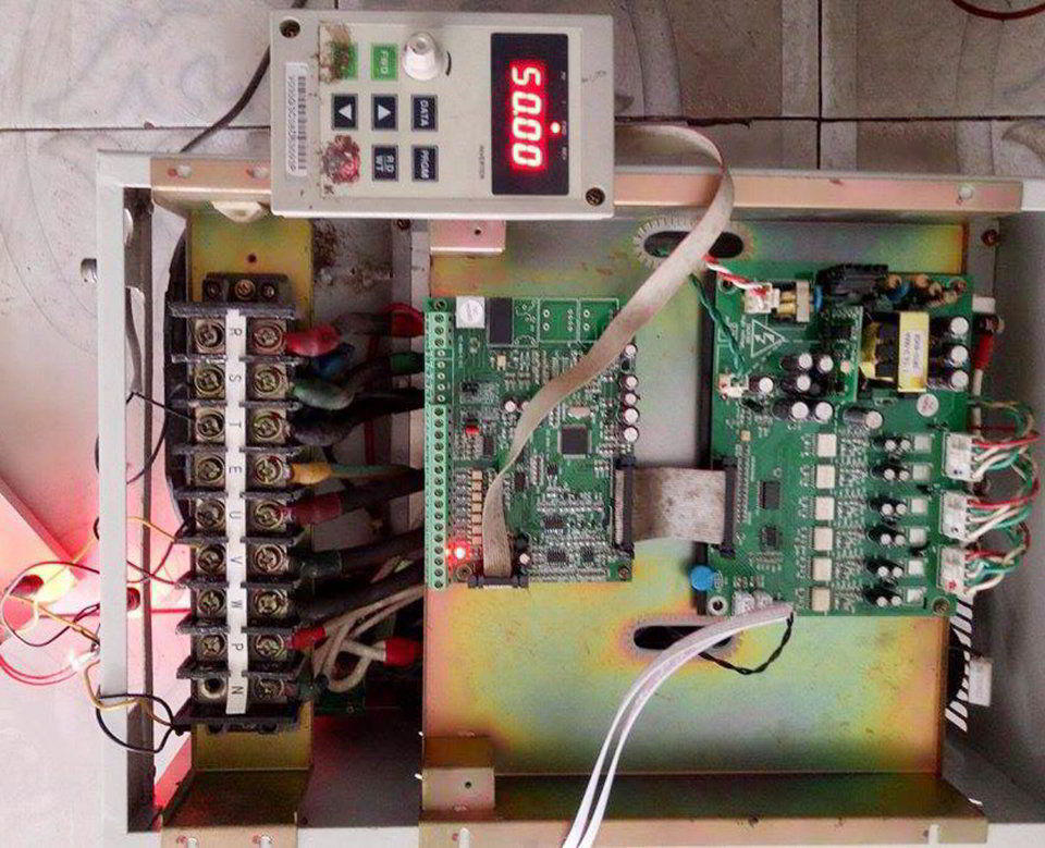
SỬA CHỮA BIẾN TẦN YOLICO
Sửa chữa biến tần Yolico tại Đà Nẵng
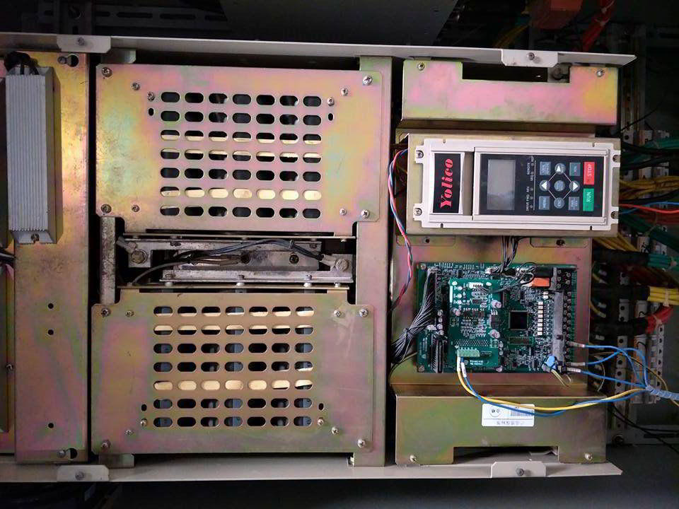
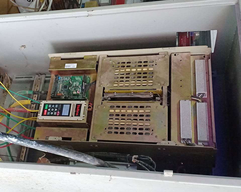
SỬA CHỮA BIẾN TẦN ABB TẠI ĐÀ NẴNG
Sửa chữa biến tần ABB
Sửa chữa biến tần ABB các dòng như ACS150, ACS355, ACS550 với công suất từ 0.75KW đến 132KW
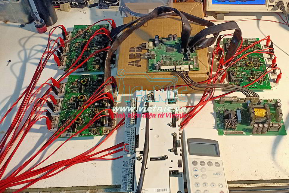
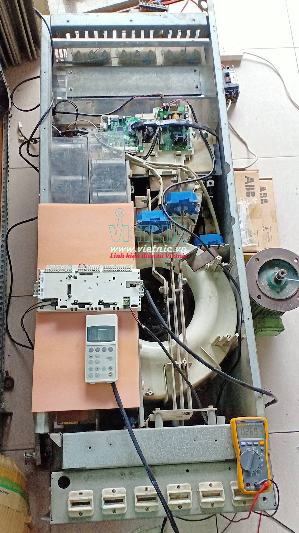
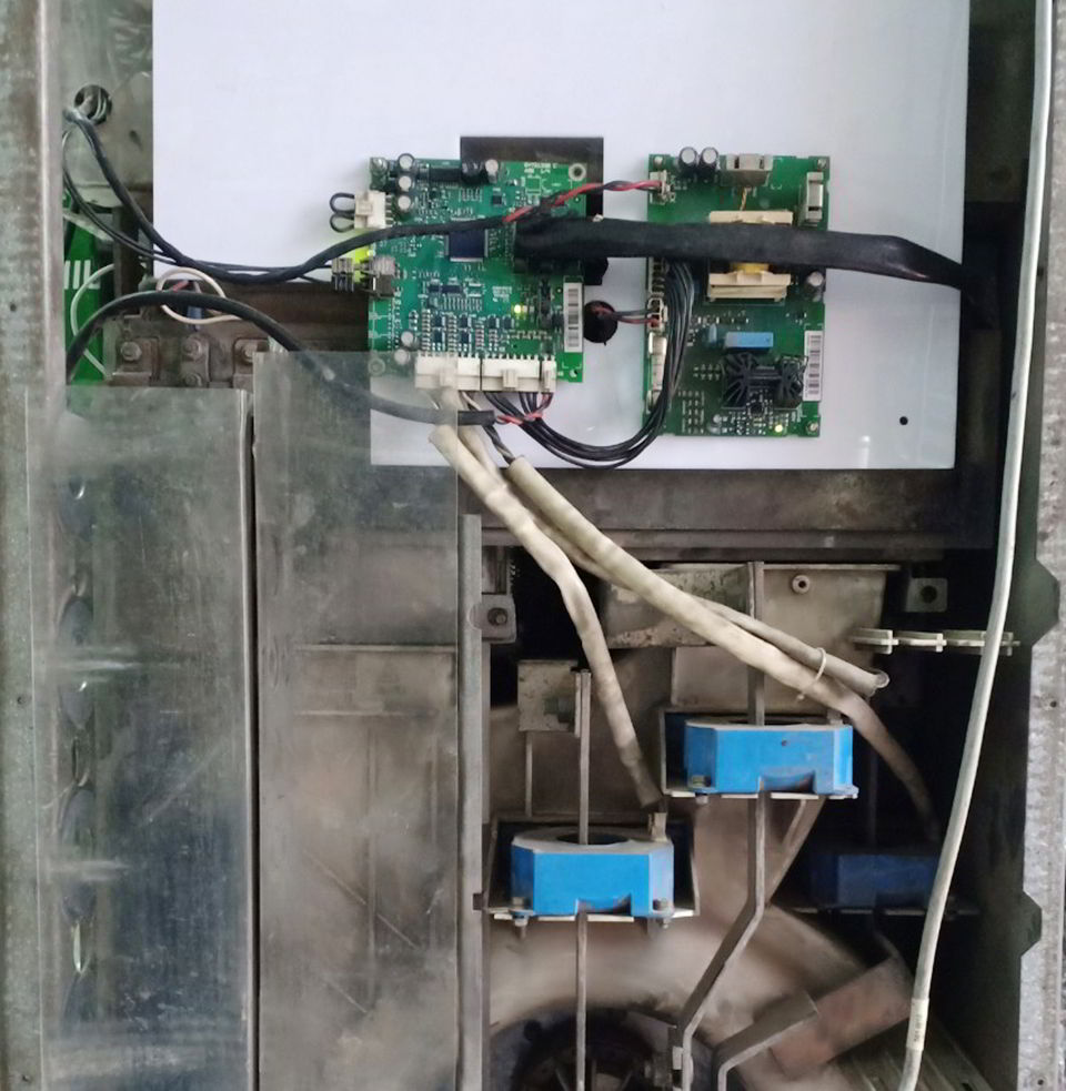
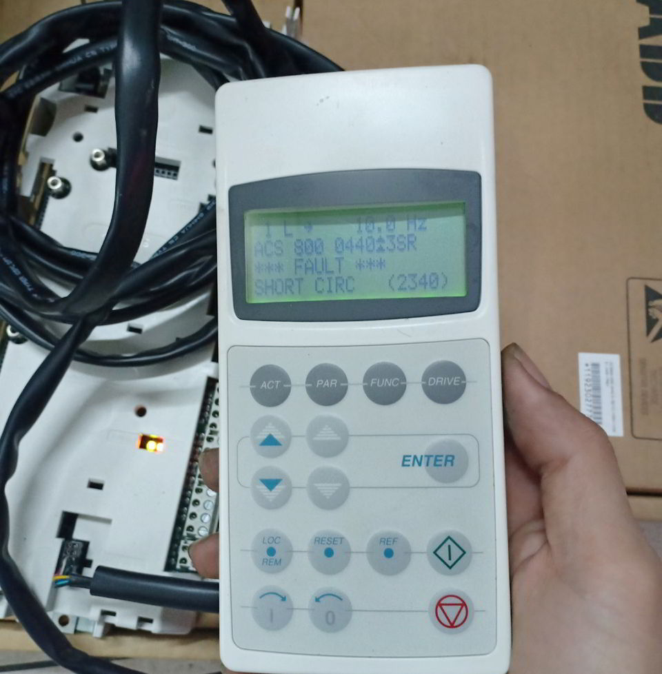
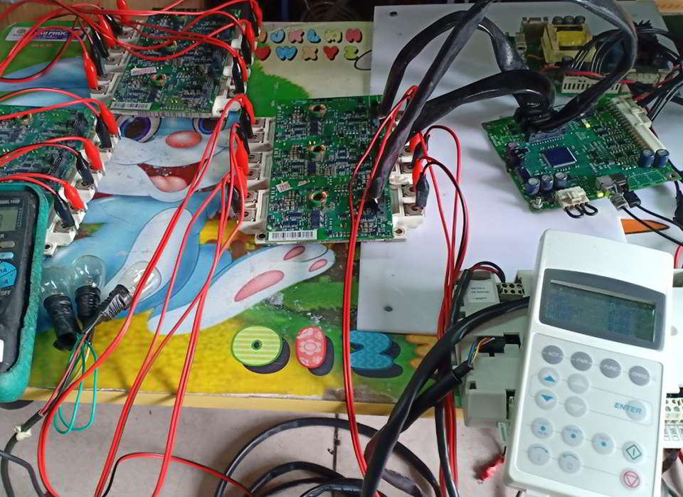
SỬA CHỮA BIẾN TẦN ABB ACS800

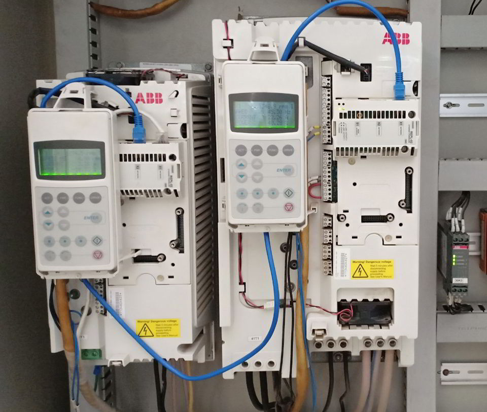
SỬA CHỮA BIẾN TẦN ACS810
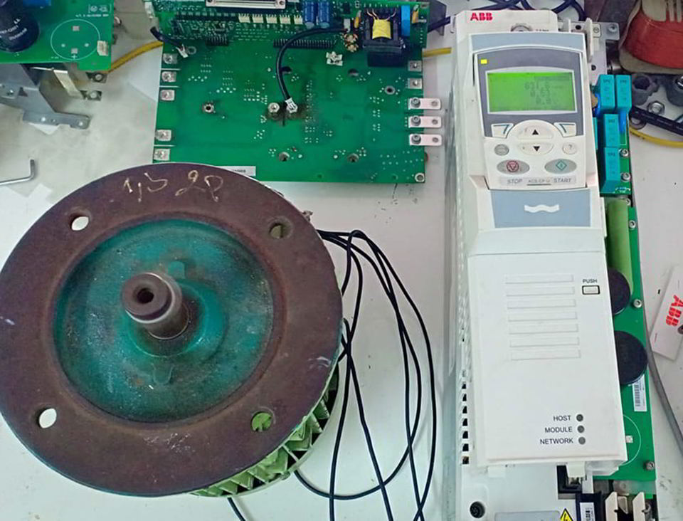
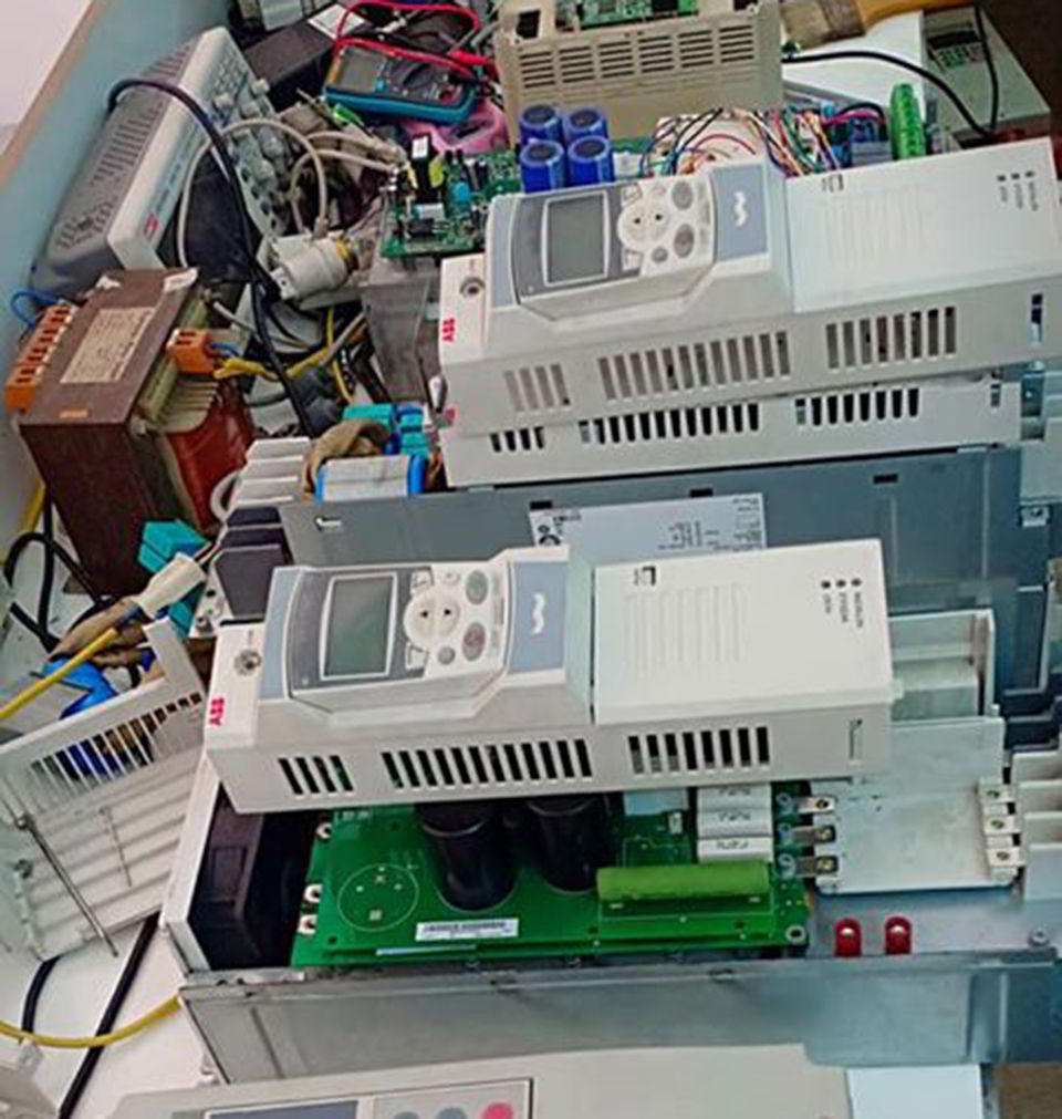
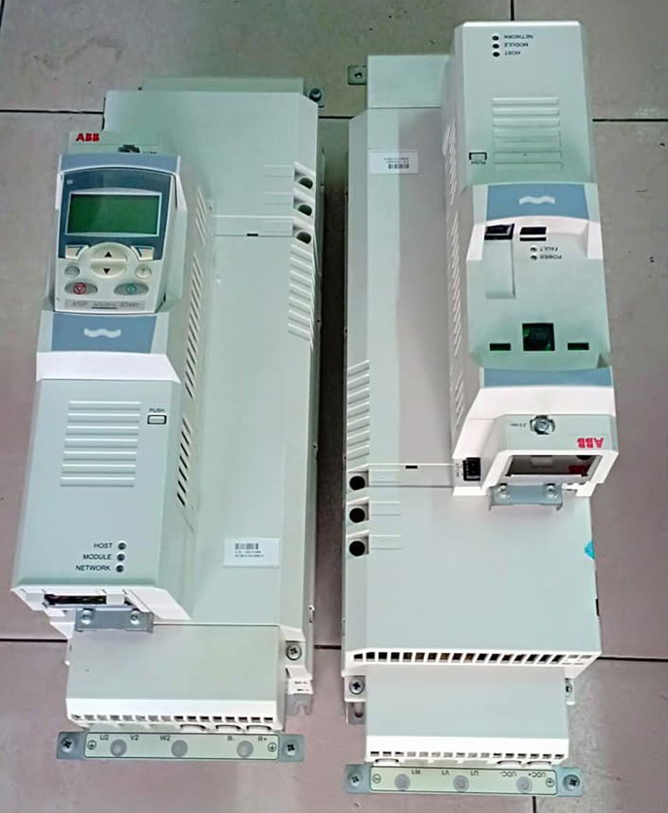
SỬA CHỮA BIẾN TẦN ACS510 ACS550
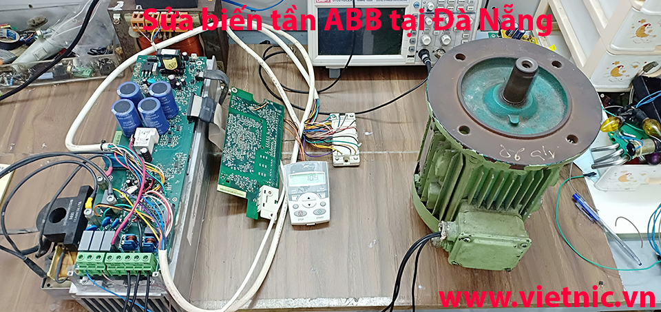
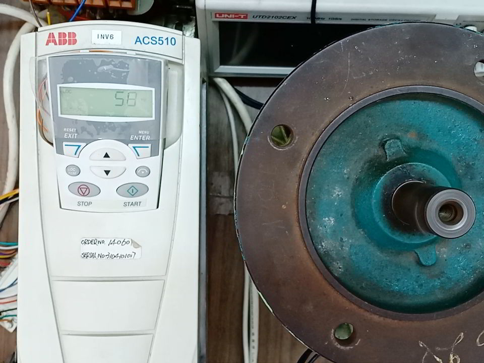
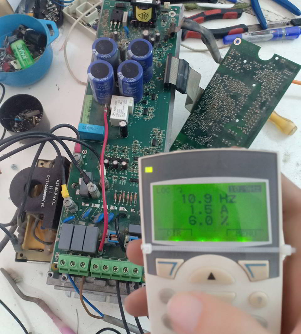
SỬA CHỮA BIẾN TẦN ACS355
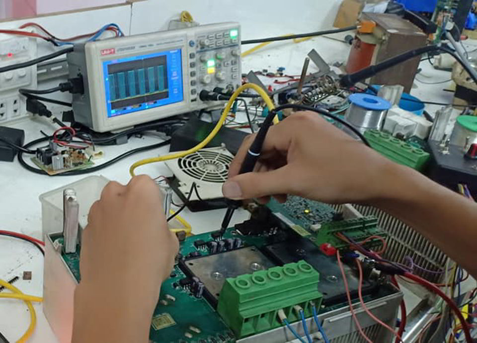
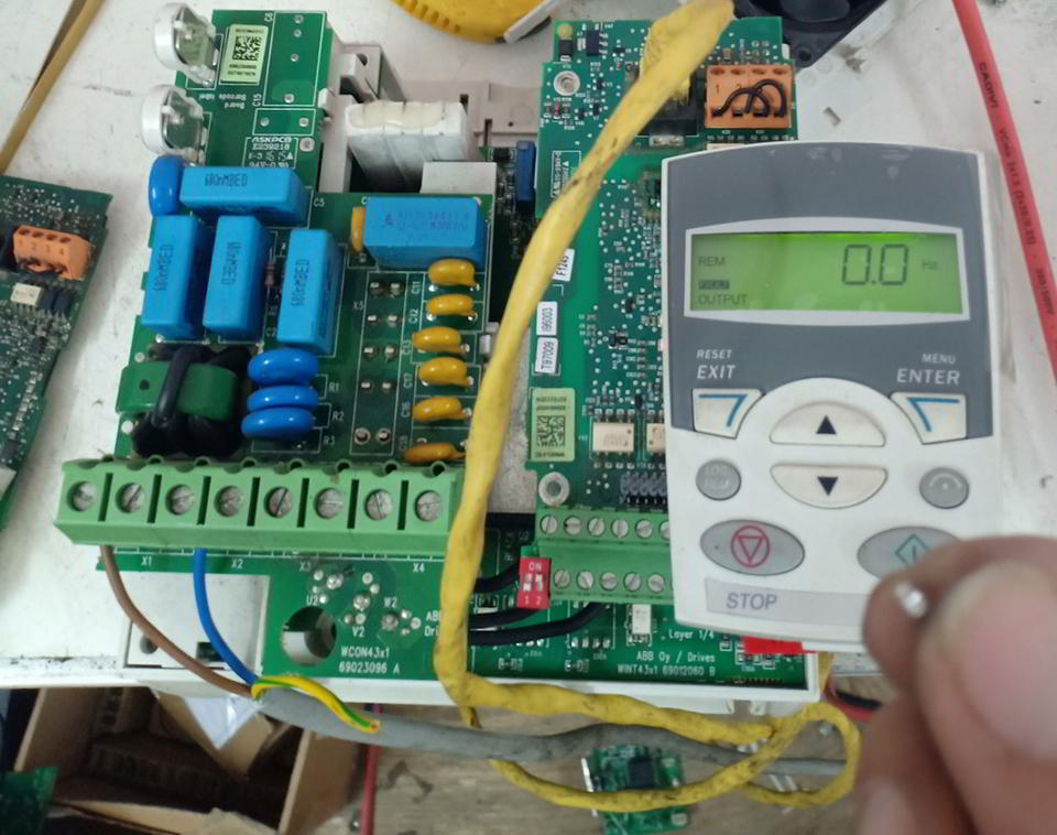
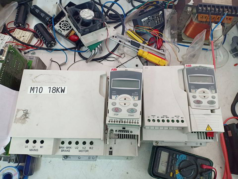
SỬA CHỮA BIẾN TẦN ABB ACS550
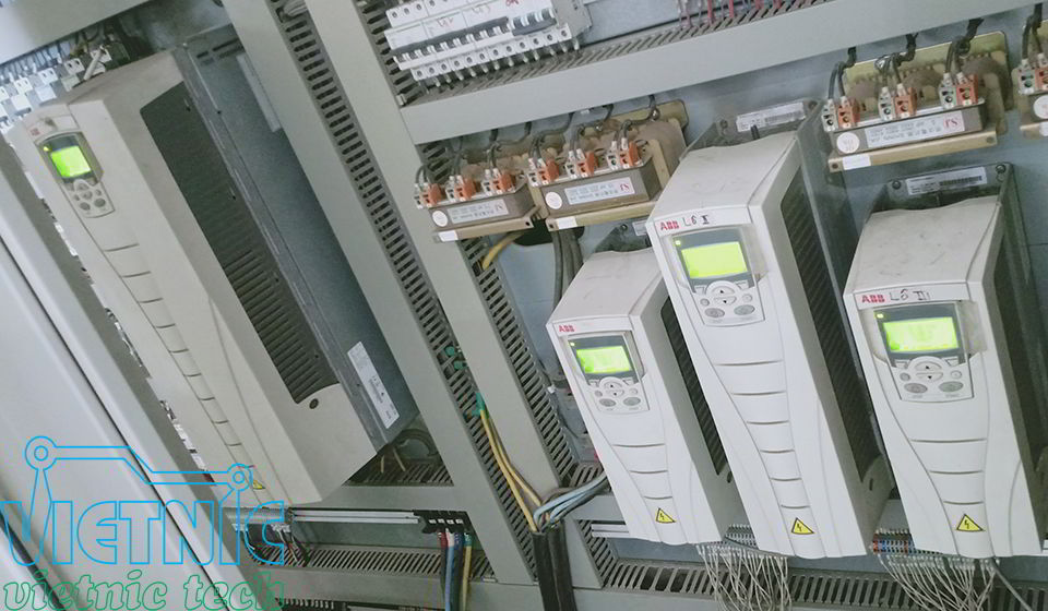
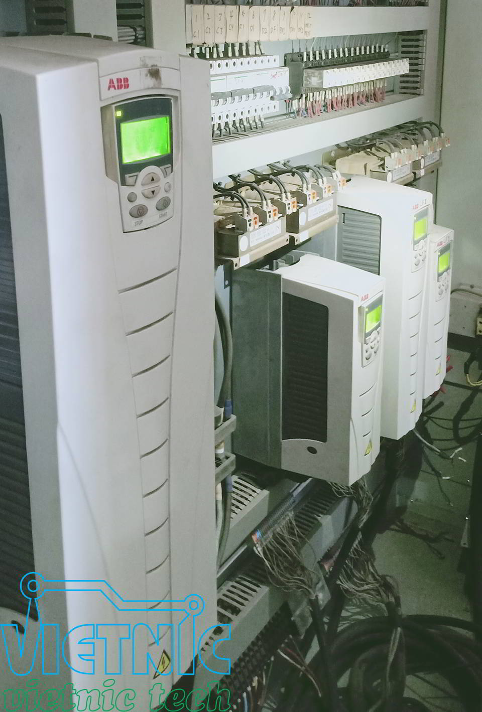
SỬA CHỮA BIẾN TẦN ABB ACS150
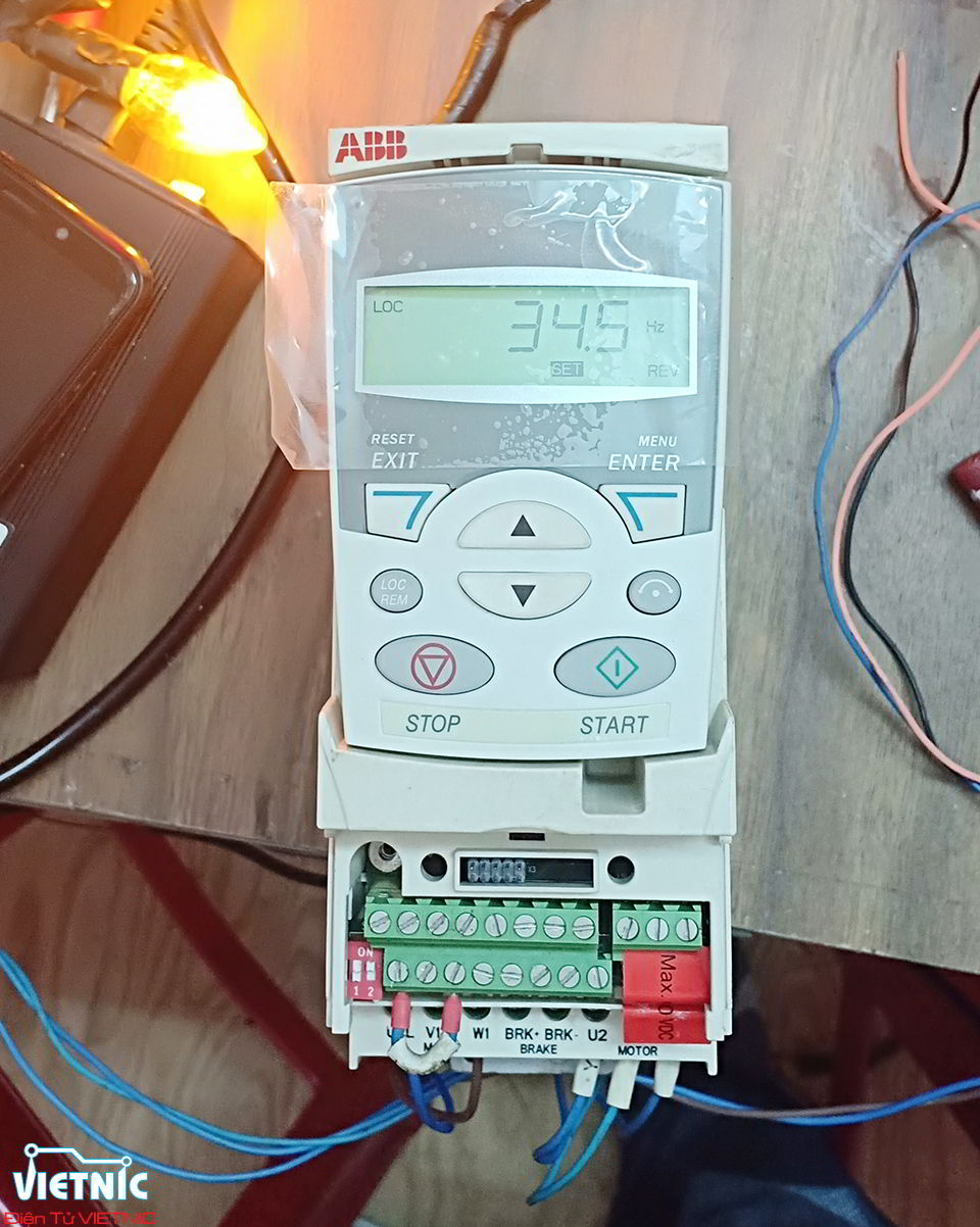
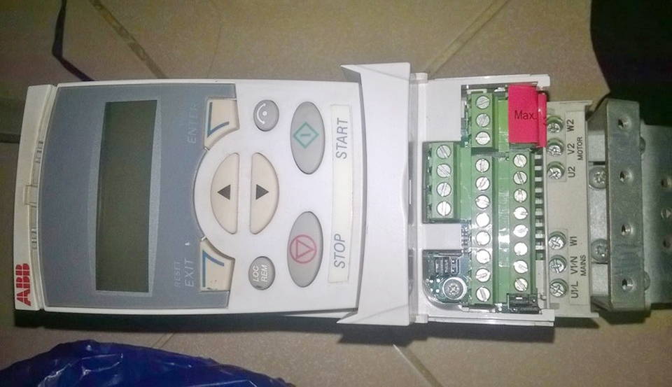
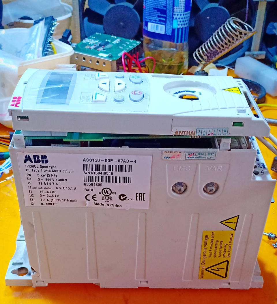
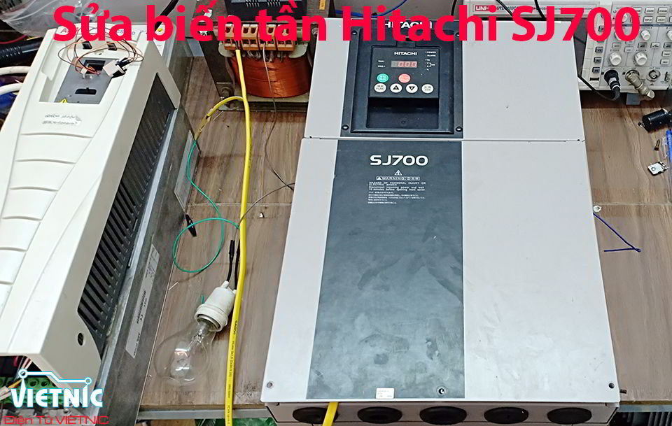
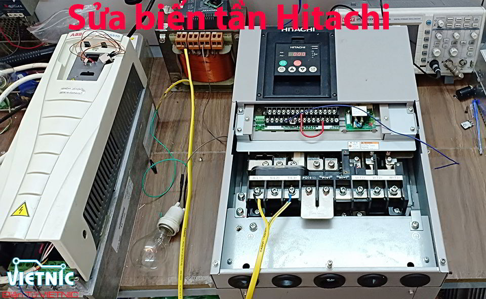
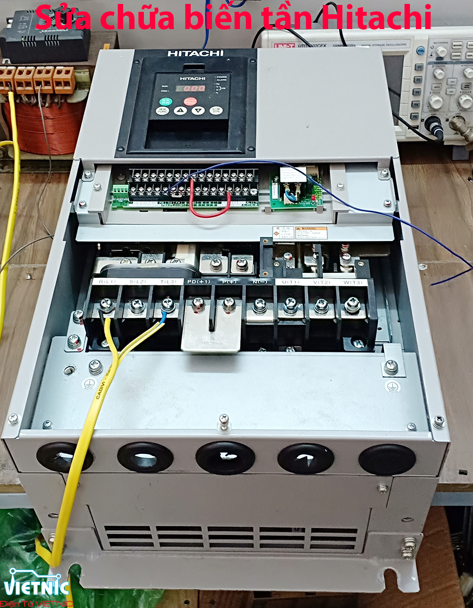
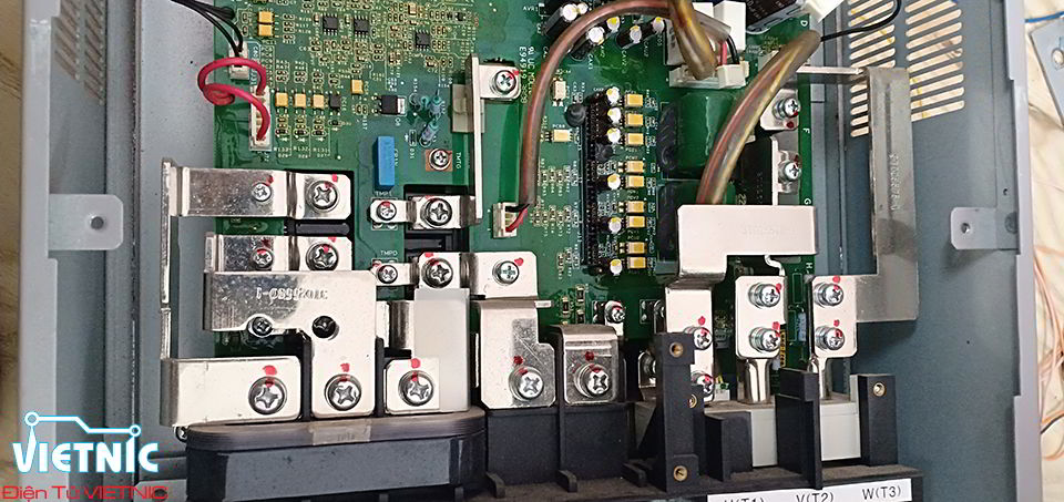
SỬA CHỮA BIẾN TẦN HITACHI
Sửa chữa biến tần Hitachi SJ700
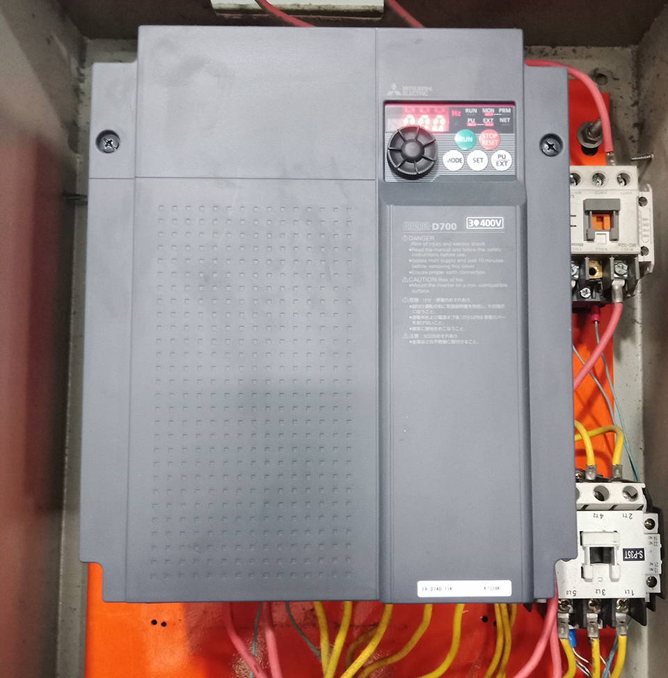
SỬA CHỮA BIẾN TẦN MITSHUBISHI
Sửa chữa biến tần Mitshubishi tại Đà Nẵng

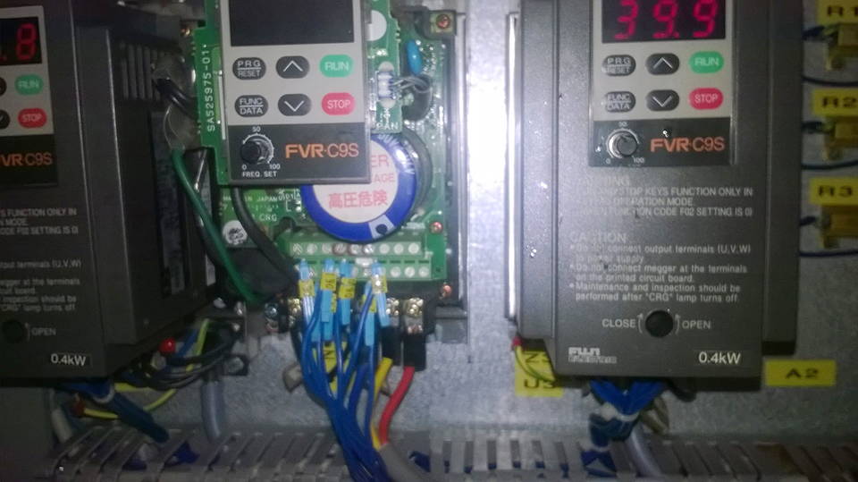
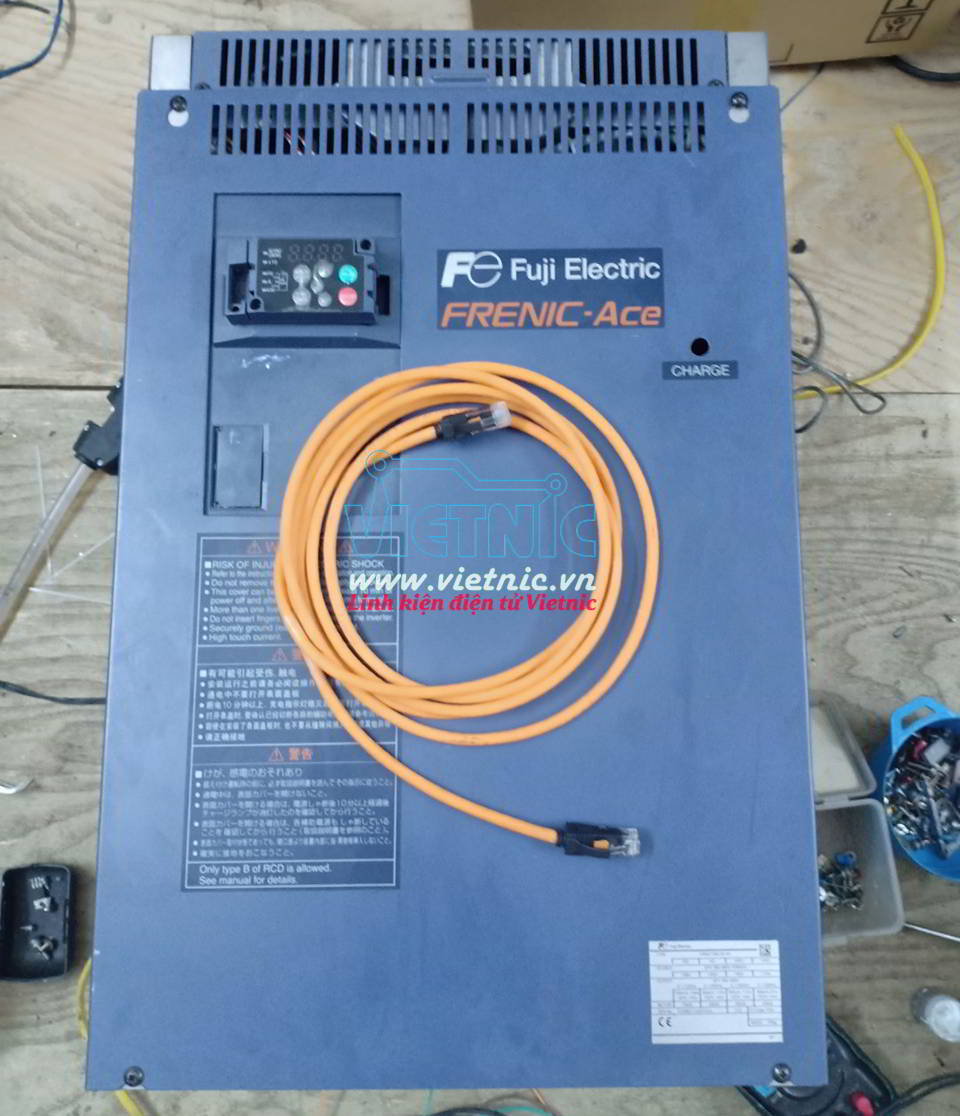
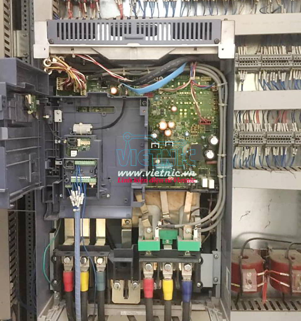
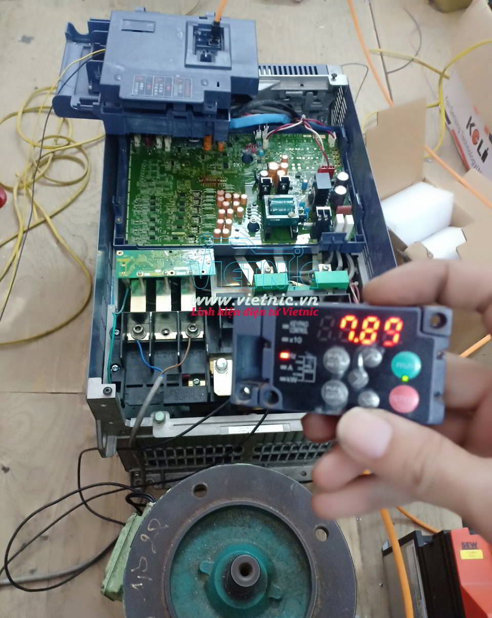
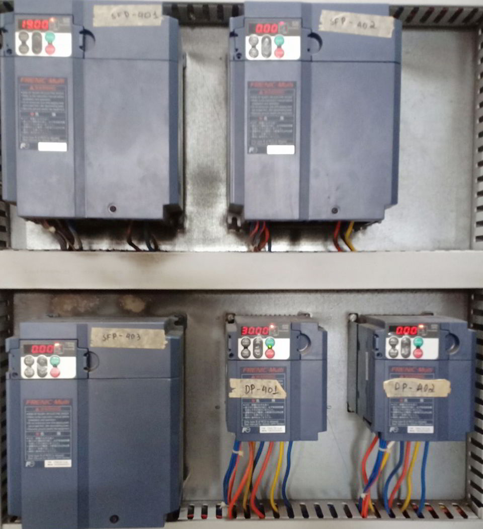
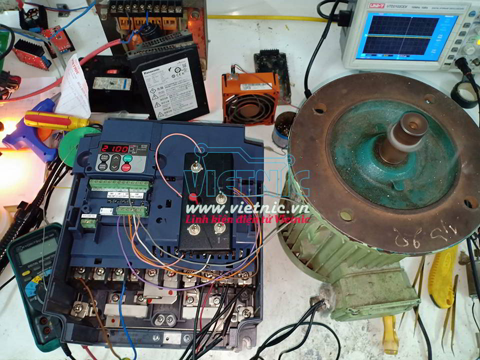
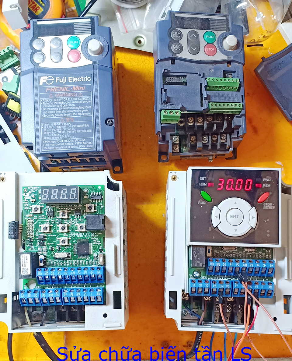
SỬA CHỮA BIẾN TẦN FUJI
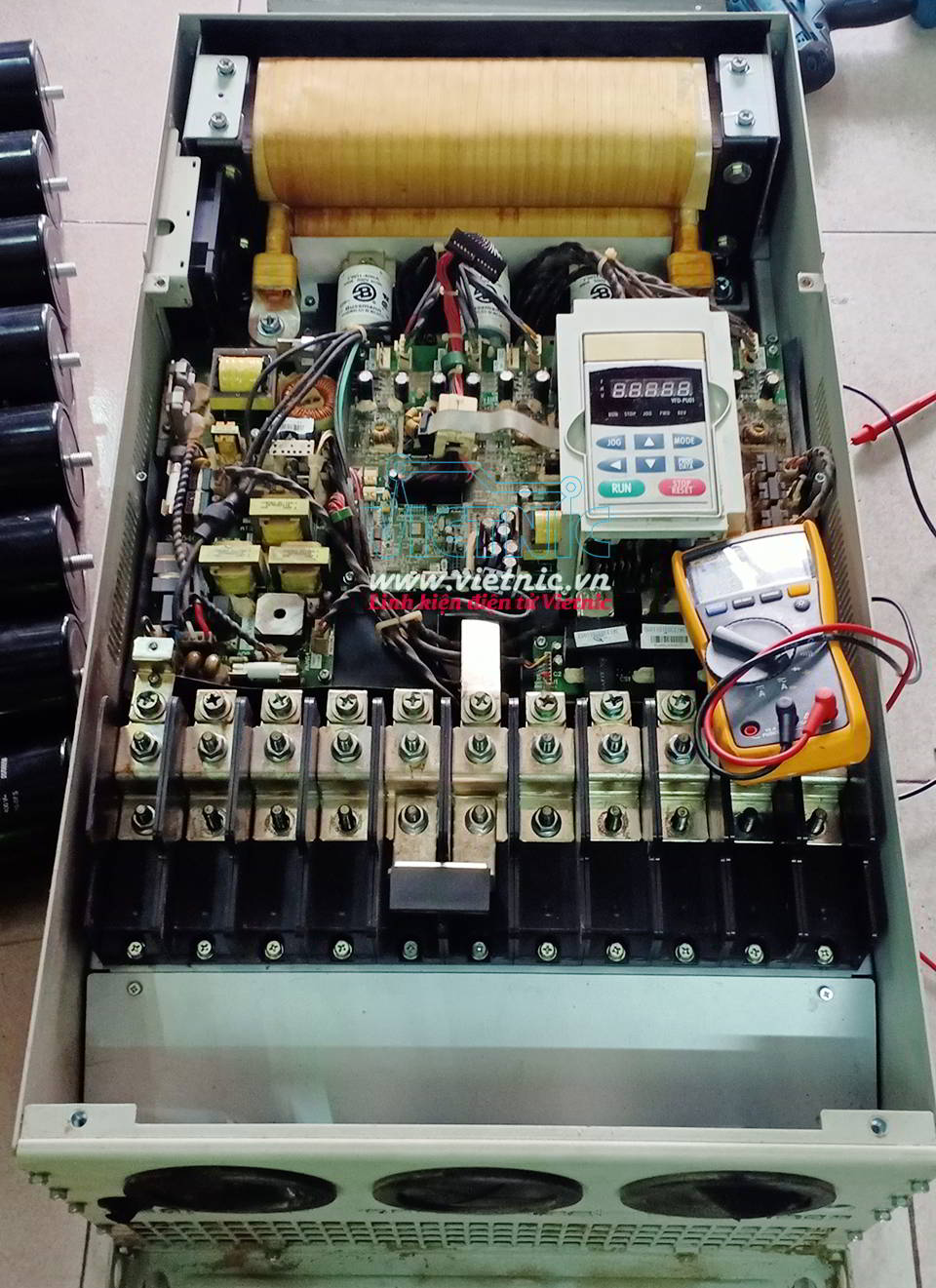
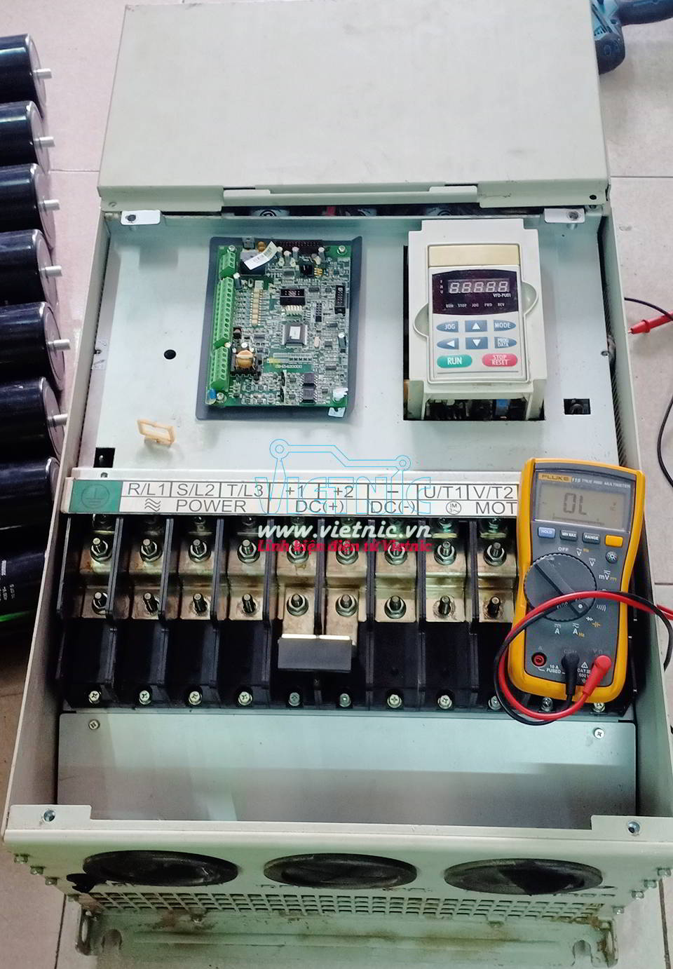
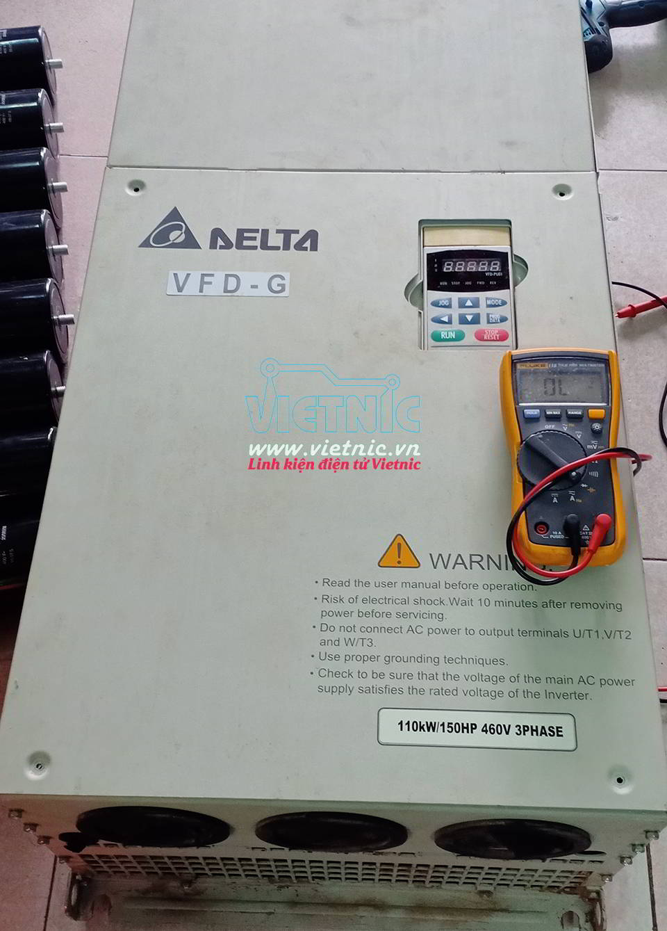
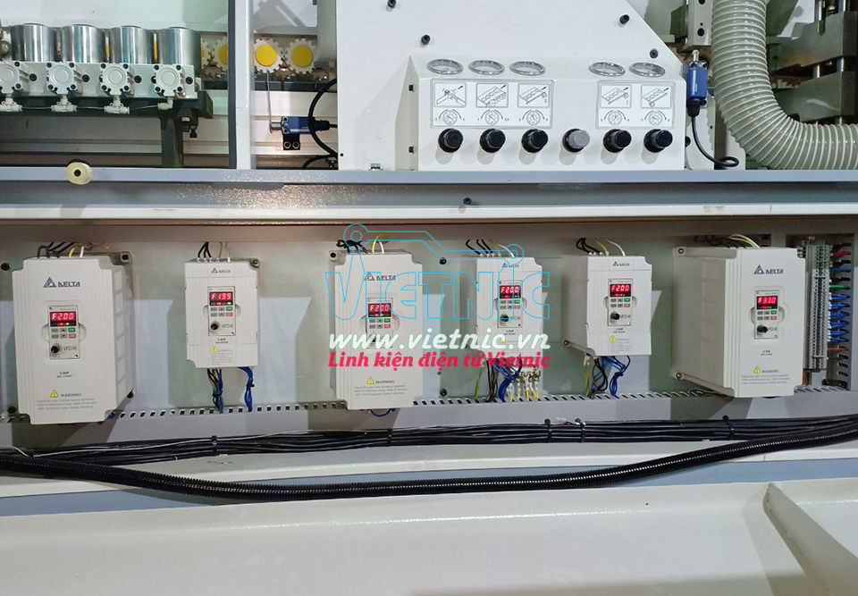
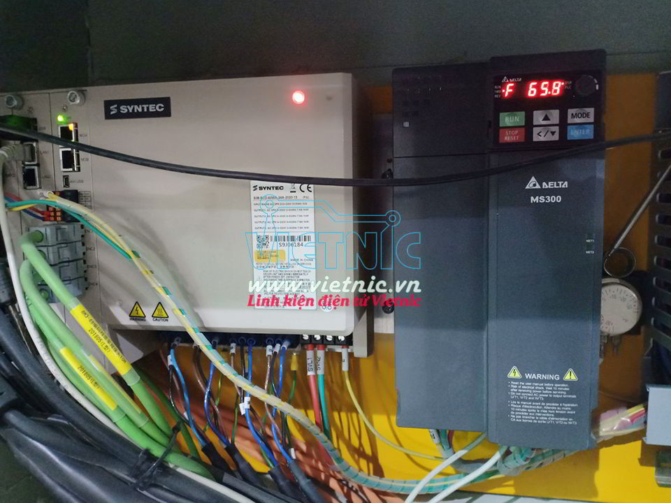
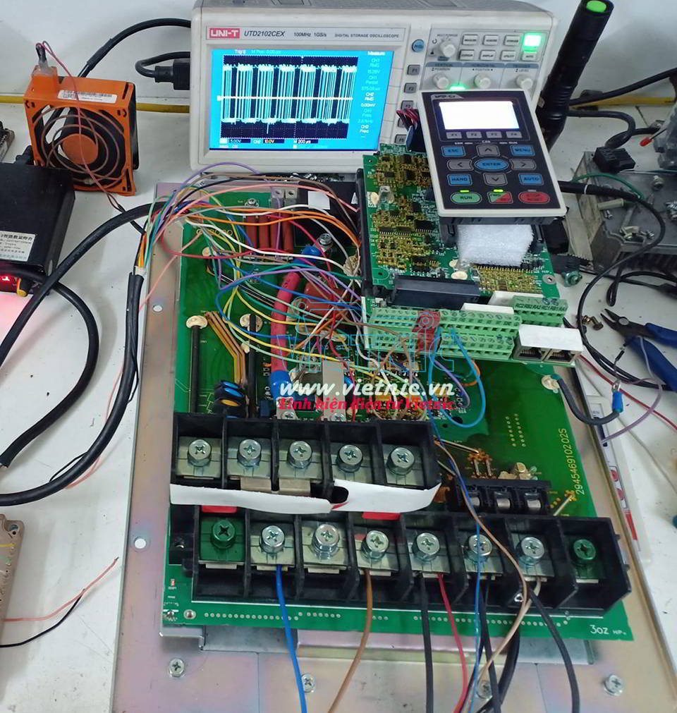
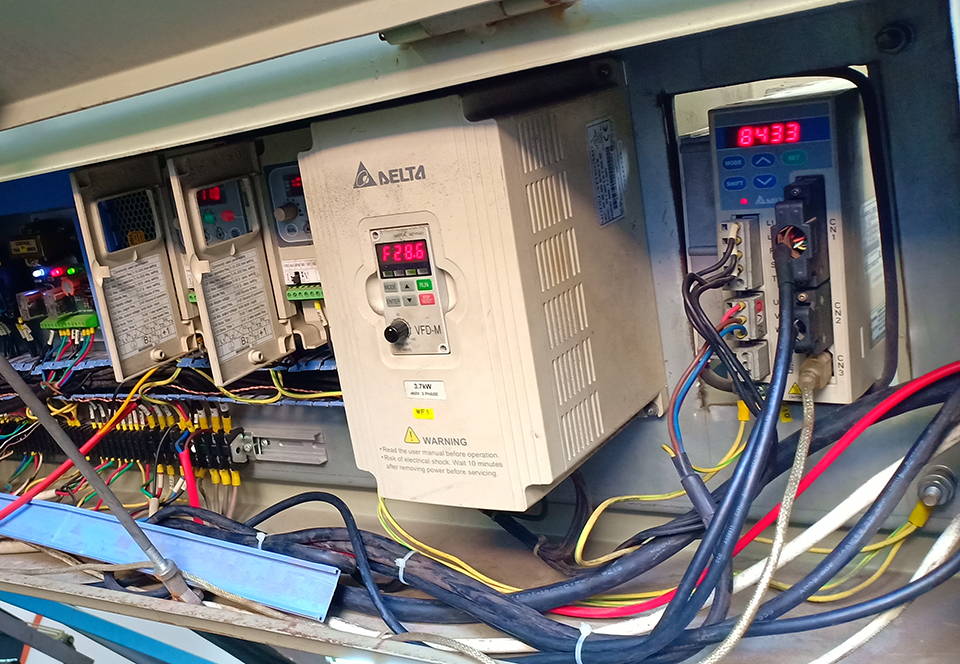
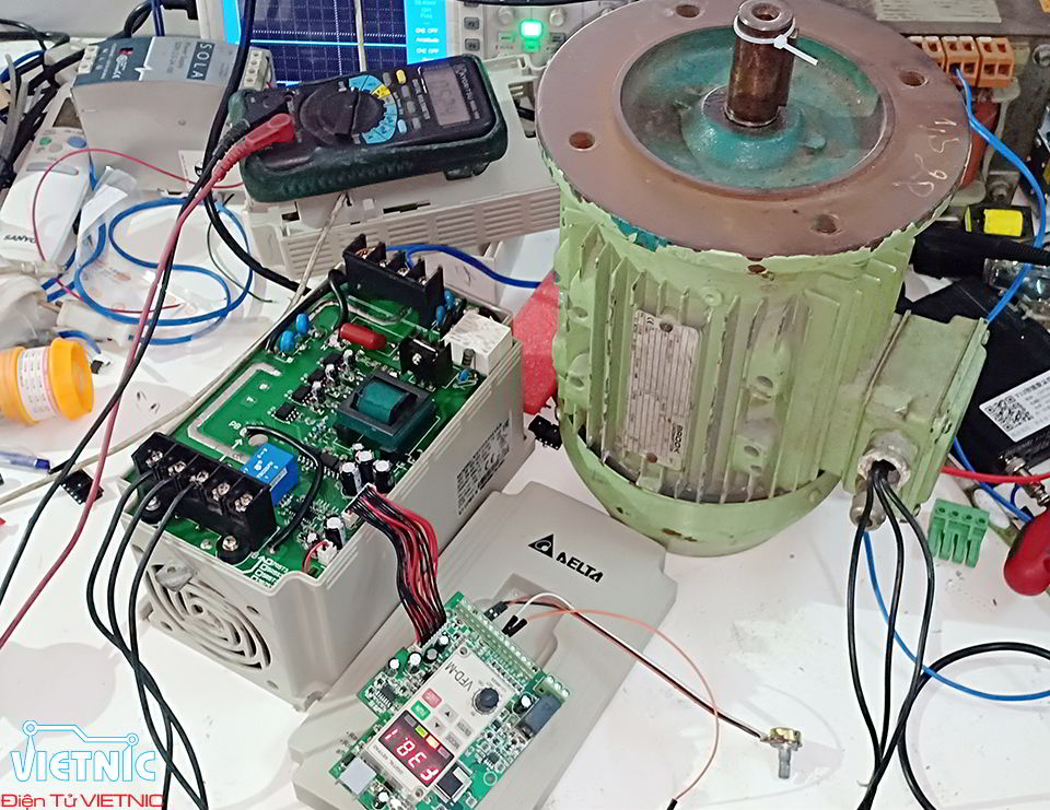
SỬA CHỮA BIẾN TẦN DELTA
Sửa chữa biến tần delta tại Đà Nẵng

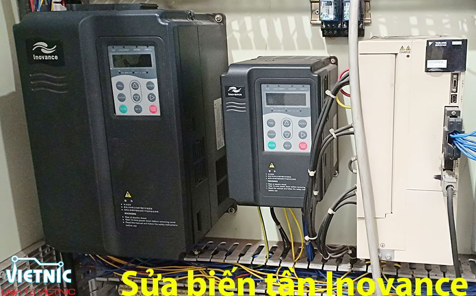
SỬA CHỮA BIẾN TẦN INOVANCE
Sửa chữa biến tần Inovance tại Đà Nẵng
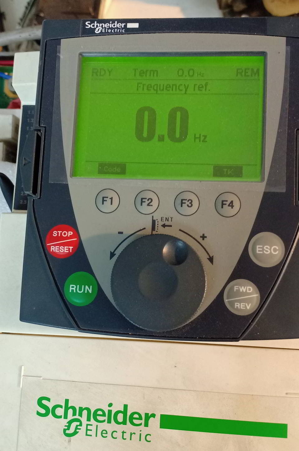
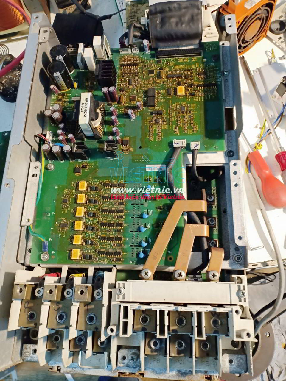
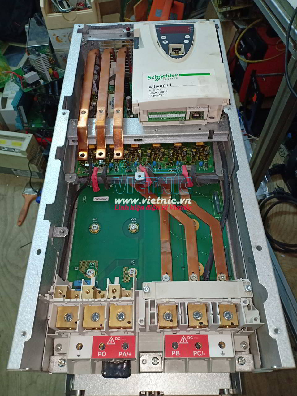
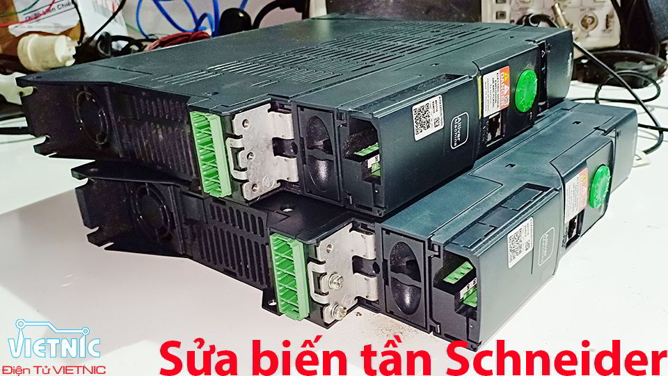
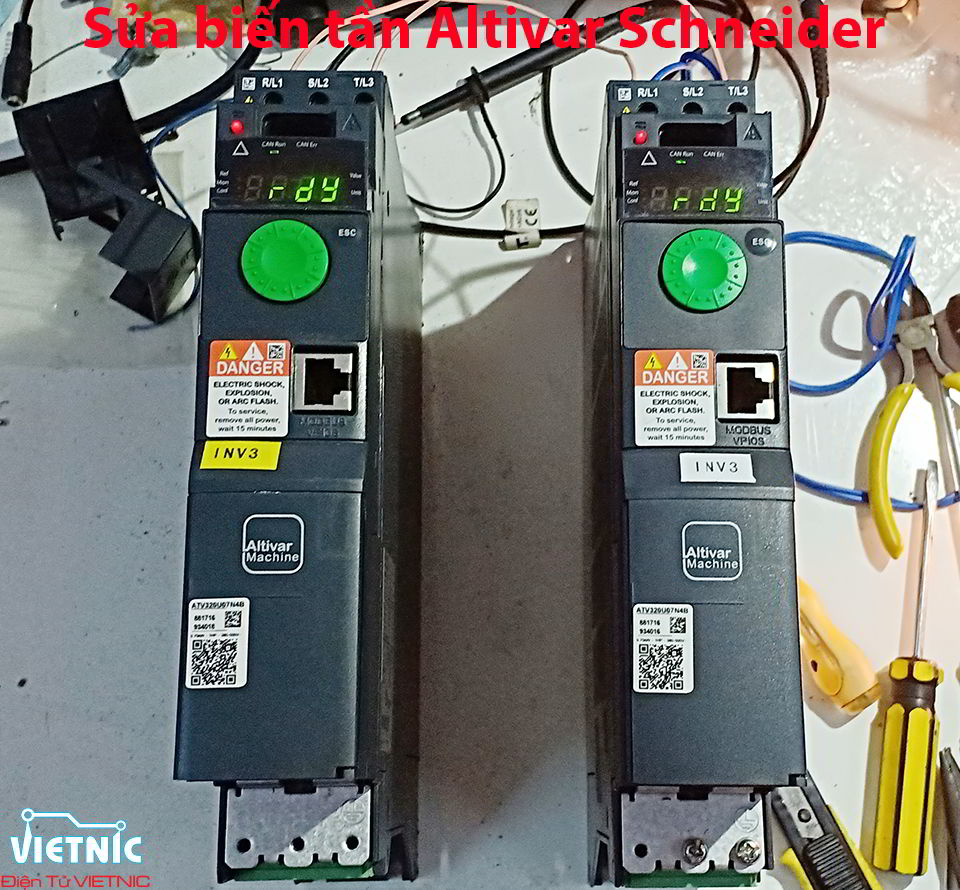
SỬA CHỮA BIẾN TẦN ALTIVAR SCHNEIDER
Sửa biến tần Altivar Schneider tại Đà Nẵng

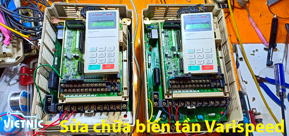
SỬA CHỮA BIẾN TẦN VARISPEED
Sửa chữa biến tần Varispeed tại Đà Nẵng
Sửa chữa biến tần Varispess 616G5, Sửa chữa biến tần Varispeed 606PC3
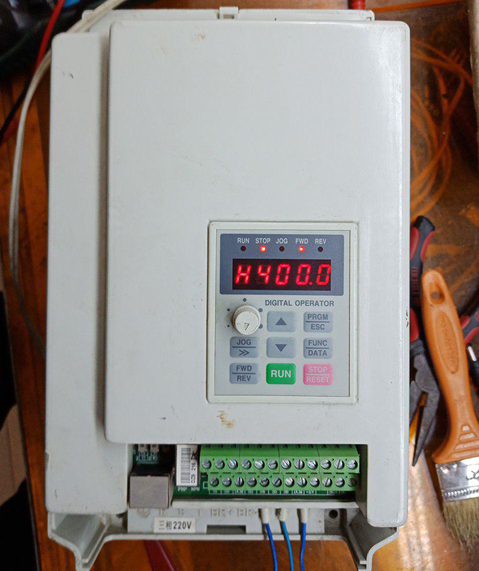
SỬA CHỮA BIẾN TẦN MÁY CNC - BIẾN TẦN SPINDLE
Sửa chữa biến tần máy CNC tại Đà Nẵng
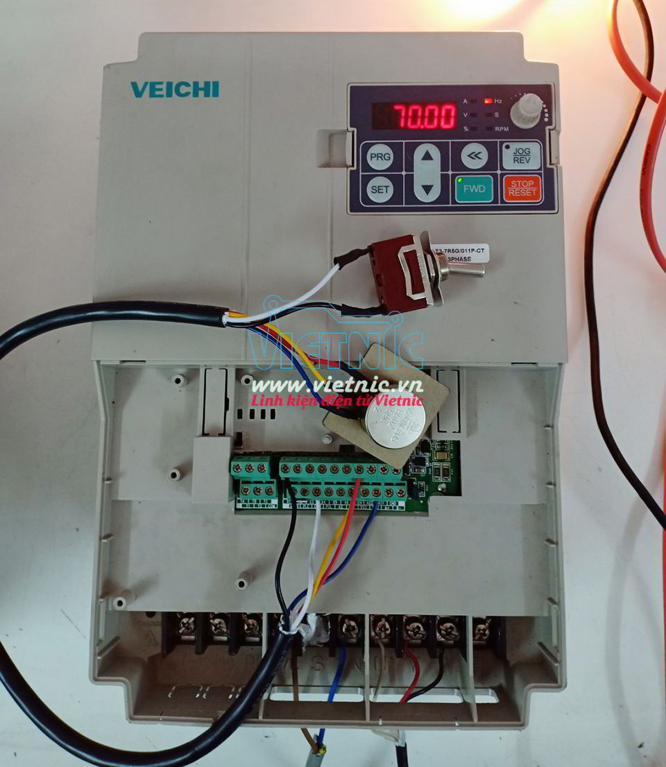
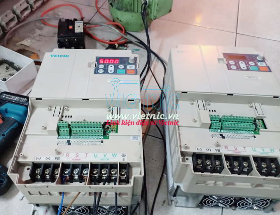
SỬA CHỮA BIẾN TẦN VEICHI

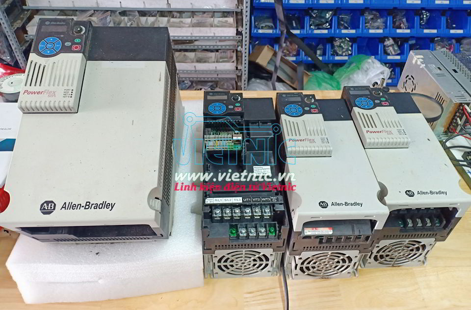
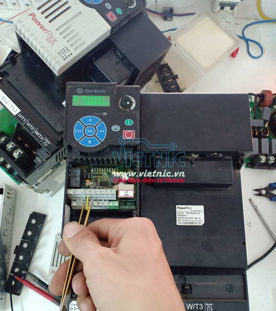
SỬA CHỮA BIẾN TẦN ALLEN-BRADLEY
SỬA CHỮA BIẾN TẦN PANASONIC
Sửa chữa biến tần Panasonic tại Đà Nẵng
ĐIỆN TỬ VIETNIC - SỬA CHỮA ĐIỆN TỬ, ĐIỆN TỬ CÔNG NGHIỆP
- Sửa chữa Biến tần, Servo driver, UPS, Máy hàn, Nguồn chuyên dụng, Sạc ắc quy, Inverters, PLC, HMI, Driver Controllers, DCS, Máy may, Thiết bị công nghiệp....
- Thiết kế mạch, lập trình theo yêu cầu các mạch ứng dụng
- Tư vấn, thiết kế tủ điện. Bảo trì thiết bị sản xuất tự động, Máy NC, CNC, Phay, Tiện, Máy đúc, Máy ép, Dập....
* Với đội ngũ là Kỹ Sư, Cử Nhân chuyên ngành Điện Tử, Cơ Điện Tử, Tự Động Hóa.., có kinh nghiệm tích lũy trong quá trình sửa chữa, cũng như thiết kế, Chúng tôi hy vọng sẽ đáp ứng được và mang lại hiệu quả cao nhất đến với quý khách hàng.
Thông tin liên hệ :
- Điện Tử VIETNIC
- Địa chỉ : 816 Tôn Đức Thắng, P. Hòa Khánh, Q. Liên Chiểu, TP. Đà Nẵng
- SĐT : 0979245175


